

Yaskawa J1000
Compact V/f frequency inverter that controls the speed of small motors up to 5.5 kW.
The Yaskawa J1000 is a compact V/f frequency inverter that controls the speed of motors from 0.1 to 5.5 kW on fans, pumps and conveyors. This Modbus RTU template reads output frequency, current, DC bus voltage, faults and maintenance monitors, and lets you start, stop and set the speed and drive parameters from ModbusCloud.
- Protocol
- Modbus RTU
- Connection
- RS485, 9600 baud
- Registers
- 180, read and write
- Brand
- Yaskawa
- Key readings
- Output frequency · Output current · DC bus voltage · Drive status · Fault code · Alarm code · Heatsink temperature · Operation time
- Available commands
- Run and stop · Frequency reference · Acceleration time · Deceleration time · Fault reset · Drive parameters
- Compatible models
- J1000 CIMR-JC (200 V single-phase, 200 V three-phase, 400 V three-phase)
- Last updated
Registers (180)
179 read, 127 write
| Name | Unit | Access | Address (Hidden until you enter your email) | Function (hidden) | Type (hidden) |
|---|---|---|---|---|---|
| Frequency Reference | Hz | Read | 64 | FC03 | uint16 |
| Output Frequency | Hz | Read | 65 | FC03 | uint16 |
| Output Current | % | Read | 66 | FC03 | uint16 |
| Output Voltage Reference | V | Read | 69 | FC03 | uint16 |
| DC Bus Voltage | V | Read | 70 | FC03 | uint16 |
| Terminal A1 Input Level | % | Read | |||
| Heatsink Temperature | °C | Read | |||
| Peak Hold Current | % | Read | |||
| Drive Status 1 | Read | ||||
| Drive Status 2 | Read | ||||
| Alarm Code | Read | ||||
| Current Fault | Read | ||||
| Previous Fault | Read | ||||
| Fault Contents 1 | Read | ||||
| Fault Contents 2 | Read | ||||
| Alarm Contents 1 | Read | ||||
| Fault Detail 1 | Read | ||||
| Fault Detail 2 | Read | ||||
| Fault Detail 3 | Read | ||||
| Fault Detail 5 | Read | ||||
| Alarm Detail 2 | Read | ||||
| Alarm Detail 3 | Read | ||||
| Alarm Detail 5 | Read | ||||
| CPF Contents 1 | Read | ||||
| CPF Contents 2 | Read | ||||
| oPE Error Number | Read | ||||
| Data Link Status | Read | ||||
| Communications Error Log | Read | ||||
| Modbus Error Code | Read | ||||
| Frequency Reference Monitor | Read | ||||
| Output Frequency Monitor | Read | ||||
| Output Voltage Monitor | V | Read | |||
| Output Current Monitor | Read | ||||
| DC Bus Voltage Monitor | V | Read | |||
| Output Frequency Percent | % | Read | |||
| Frequency Reference After Soft Starter | % | Read | |||
| Frequency Reference Percent | % | Read | |||
| Input Terminal Status | Read | ||||
| Output Terminal Status | Read | ||||
| Input Terminal Status U1-10 | Read | ||||
| Output Terminal Status U1-11 | Read | ||||
| Accumulated Operation Time | h | Read | |||
| Operation Time 10 h Part | h | Read | |||
| Operation Time 1 h Part | h | Read | |||
| Cooling Fan Maintenance | % | Read | |||
| Capacitor Maintenance | % | Read | |||
| Soft Charge Relay Maintenance | % | Read | |||
| IGBT Maintenance | % | Read | |||
| Drive Rated Current | Read | ||||
| Product Code | Read | ||||
| ROM ID | Read | ||||
| Flash ID | Read | ||||
| LED Check | Read | ||||
| Operation Command | Read and write | ||||
| Frequency Reference Command | Read and write | ||||
| Analog Output AM Setting | Read and write | ||||
| Digital Output Setting | Read and write | ||||
| Control Selection | Read and write | ||||
| Enter Command | Write | ||||
| Access Level Selection | Read and write | ||||
| Initialize Parameters | Read and write | ||||
| Password | Read and write | ||||
| Password Setting | Read and write | ||||
| Frequency Reference Selection | Read and write | ||||
| Run Command Selection | Read and write | ||||
| Stopping Method Selection | Read and write | ||||
| Reverse Operation Selection | Read and write | ||||
| LOCAL REMOTE Run Selection | Read and write | ||||
| Run Command in Programming Mode | Read and write | ||||
| Phase Order Selection | Read and write | ||||
| Run Command at Power Up | Read and write | ||||
| DC Injection Braking Current | % | Read and write | |||
| DC Injection Time at Start | s | Read and write | |||
| DC Injection Time at Stop | s | Read and write | |||
| Acceleration Time 1 | s | Read and write | |||
| Deceleration Time 1 | s | Read and write | |||
| Acceleration Time 2 | s | Read and write | |||
| Deceleration Time 2 | s | Read and write | |||
| Fast Stop Time | s | Read and write | |||
| S-Curve at Accel Start | s | Read and write | |||
| S-Curve at Accel End | s | Read and write | |||
| S-Curve at Decel Start | s | Read and write | |||
| S-Curve at Decel End | s | Read and write | |||
| Slip Compensation Gain | Read and write | ||||
| Slip Compensation Delay Time | ms | Read and write | |||
| Torque Compensation Gain | Read and write | ||||
| Drive Duty Selection | Read and write | ||||
| Carrier Frequency Selection | Read and write | ||||
| Carrier Frequency Upper Limit | Read and write | ||||
| Carrier Frequency Lower Limit | Read and write | ||||
| Carrier Frequency Proportional Gain | Read and write | ||||
| Frequency Reference 1 | Hz | Read and write | |||
| Frequency Reference 2 | Hz | Read and write | |||
| Frequency Reference 3 | Hz | Read and write | |||
| Frequency Reference 4 | Hz | Read and write | |||
| Frequency Reference 5 | Hz | Read and write | |||
| Frequency Reference 6 | Hz | Read and write | |||
| Frequency Reference 7 | Hz | Read and write | |||
| Frequency Reference 8 | Hz | Read and write | |||
| Jog Frequency Reference | Hz | Read and write | |||
| Frequency Reference Upper Limit | % | Read and write | |||
| Frequency Reference Lower Limit | % | Read and write | |||
| Jump Frequency 1 | Hz | Read and write | |||
| Jump Frequency 2 | Hz | Read and write | |||
| Jump Frequency Width | Hz | Read and write | |||
| Frequency Reference Hold | Read and write | ||||
| Input Voltage Setting | V | Read and write | |||
| V/f Pattern Selection | Read and write | ||||
| Maximum Output Frequency | Hz | Read and write | |||
| Maximum Output Voltage | V | Read and write | |||
| Base Frequency | Hz | Read and write | |||
| Middle Output Frequency | Hz | Read and write | |||
| Middle Output Frequency Voltage | V | Read and write | |||
| Minimum Output Frequency | Hz | Read and write | |||
| Minimum Output Frequency Voltage | V | Read and write | |||
| Motor Rated Current | Read and write | ||||
| Motor Rated Slip | Hz | Read and write | |||
| Motor No-Load Current | Read and write | ||||
| Motor Line-to-Line Resistance | Ω | Read and write | |||
| Digital Input S1 Function | Read and write | ||||
| Digital Input S2 Function | Read and write | ||||
| Digital Input S3 Function | Read and write | ||||
| Digital Input S4 Function | Read and write | ||||
| Digital Input S5 Function | Read and write | ||||
| Relay Output MA MB MC Function | Read and write | ||||
| Terminal A1 Signal Level | Read and write | ||||
| Terminal A1 Gain | % | Read and write | |||
| Terminal A1 Bias | % | Read and write | |||
| Analog Input Filter Time | s | Read and write | |||
| Analog Output AM Monitor Selection | Read and write | ||||
| Analog Output AM Gain | % | Read and write | |||
| Analog Output AM Bias | % | Read and write | |||
| Slave Address | Read and write | ||||
| Communication Speed | Read and write | ||||
| Communication Parity | Read and write | ||||
| Stopping Method After Comm Error | Read and write | ||||
| Comm Fault Detection | Read and write | ||||
| Drive Transmit Wait Time | ms | Read and write | |||
| RTS Control Selection | Read and write | ||||
| Run Command Method | Read and write | ||||
| Modbus Frequency Unit | Read and write | ||||
| Motor Overload Protection | Read and write | ||||
| Motor Overload Protection Time | min | Read and write | |||
| Continuous Electrothermal Operation | Read and write | ||||
| Momentary Power Loss Operation | Read and write | ||||
| Stall Prevention During Accel | Read and write | ||||
| Stall Prevention Level Accel | % | Read and write | |||
| Stall Prevention During Decel | Read and write | ||||
| Stall Prevention During Run | Read and write | ||||
| Stall Prevention Level Run | % | Read and write | |||
| Speed Agreement Detection Level | Hz | Read and write | |||
| Speed Agreement Detection Selection | Read and write | ||||
| Number of Auto Restart Attempts | Read and write | ||||
| Torque Detection Selection 1 | Read and write | ||||
| Torque Detection Level 1 | % | Read and write | |||
| Torque Detection Time 1 | s | Read and write | |||
| Braking Resistor Protection | Read and write | ||||
| Input Phase Loss Protection | Read and write | ||||
| Heatsink Fan Operation | Read and write | ||||
| Ambient Temperature Setting | °C | Read and write | |||
| Soft Current Limit Selection | Read and write | ||||
| Installation Method Selection | Read and write | ||||
| Carrier Frequency Reduction | Read and write | ||||
| Hunting Prevention Gain | Read and write | ||||
| Overexcitation Deceleration Gain | Read and write | ||||
| Monitor After Power Up | Read and write | ||||
| Display Unit Selection | Read and write | ||||
| STOP Key Function | Read and write | ||||
| Drive Model Selection | Read and write | ||||
| Frequency Setting Method | Read and write | ||||
| Operator Disconnect Operation | Read and write | ||||
| Copy Function Selection | Read and write | ||||
| Copy Allowed Selection | Read and write | ||||
| Operation Time Setting | h | Read and write | |||
| Operation Time Selection | Read and write | ||||
| Fan Operation Time Setting | h | Read and write | |||
| Capacitor Maintenance Setting | % | Read and write | |||
| Soft Charge Relay Maintenance Setting | % | Read and write | |||
| IGBT Maintenance Setting | % | Read and write | |||
| U2 Initialization | Read and write |
Loading registers…
Send your device list
If a device is not in the library yet, we build the template for free as soon as we have the register data.
Use cases
- Show output frequency, current and DC bus voltage of each drive on a dashboard next to the fan or pump it controls.
- Get an email alert when the current fault code is not zero, so you know a drive has tripped before the customer calls.
- Track the capacitor and cooling fan maintenance monitors to plan replacement before the drive fails.
- Change acceleration and deceleration times or preset speeds remotely without driving to the site.
- Keep a year of output frequency and current history to compare load before and after a change in the installation.
Installation
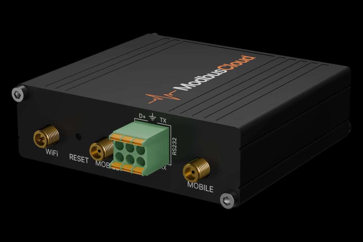
Fit the SI-485/J interface option on the drive and connect its RS-485 terminals to RS485 A and B of the ModbusCloud Gateway, with termination at both bus ends.
Set H5-01 (address), H5-02 (speed) and H5-03 (parity) on the drive and cycle power. Default is address 31, 9600 baud, no parity.
To control the drive over Modbus, set b1-01 and b1-02 to 2.
In ModbusCloud, add a Modbus device with the same address and settings and import this template.
Check that output frequency and DC bus voltage come in. Product Code should read J0.
Things to watch for
The drive does not answer at all. What should I check?
Check that the SI-485/J option is fitted, that H5-01 is not 0 and that address, speed and parity match. H5 changes only take effect after a power cycle. Swap A and B if it still stays silent, and check the termination at both ends of the bus.
I write a parameter, but after a power cycle the old value is back.
The drive keeps Modbus parameter writes in RAM only. Write 0 to the Enter Command register to store them in EEPROM. The EEPROM allows about 100000 writes, so do not send Enter on every change in an automation.
Why does the drive ignore my run command and frequency reference?
The drive only follows Modbus when b1-01 (frequency reference) and b1-02 (run command) are set to 2. Also check H5-12 for the meaning of bits 0 and 1 of the operation command, and H5-13 for the unit of the frequency reference.
What should I watch out for when writing registers?
Writes go straight into the running drive. A wrong acceleration time, motor current or stall prevention level can trip the drive or stress the motor. Change one value at a time, check it on site where you can, and only enable writing for people who know the application.
The drive trips on a CE fault after a while.
With H5-05 = 1 the drive raises a communication error when it gets no message for 2 seconds. ModbusCloud reads at the interval you set, by default every 5 minutes. Set H5-05 to 0 when the drive is controlled by terminals and only monitored.
More Yaskawa templates


Want to see how it works?