


ABB ACH580
HVAC frequency converter for fans and pumps with speed, power, energy, faults and all parameters over Modbus RTU.
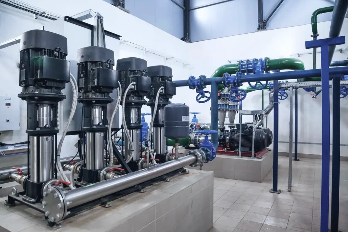
The ABB ACH580 is a frequency converter that controls fans, pumps and compressors in heating, ventilation and air conditioning systems. This Modbus RTU template reads speed, power, energy, temperatures, faults and PID values, and lets you write the start command, speed reference, PID setpoints and other parameters from ModbusCloud.
- Protocol
- Modbus RTU
- Connection
- RS485, 19200 baud
- Registers
- 1491, read and write
- Brand
- ABB
- Key readings
- Motor speed · Output frequency · Motor current · Output power · Energy · Fault code · Drive temperature · PID feedback
- Available commands
- Start and stop · Speed reference · PID setpoint · Ramp times · Speed limits · Timer functions
- Compatible models
- ACH580-01 · ACH580-04 · ACH580-07 · ACH580-31 · ACH580-34
- Last updated
Registers (1491)
1491 read, 1202 write
| Name | Unit | Access | Address (Hidden until you enter your email) | Function (hidden) | Type (hidden) |
|---|---|---|---|---|---|
| Modbus Control Word | Read and write | 0 | FC03 / FC06 | uint16 | |
| Modbus Reference 1 | Read and write | 1 | FC03 / FC06 | int16 | |
| Modbus Reference 2 | Read and write | 2 | FC03 / FC06 | int16 | |
| Modbus Status Word | Read | 3 | FC03 | uint16 | |
| Modbus Actual Value 1 | Read | 4 | FC03 | int16 | |
| Modbus Actual Value 2 | Read | ||||
| Modbus Data IO 7 | Read and write | ||||
| Modbus Data IO 8 | Read and write | ||||
| Modbus Data IO 9 | Read and write | ||||
| Modbus Data IO 10 | Read and write | ||||
| Modbus Data IO 11 | Read and write | ||||
| Modbus Data IO 12 | Read and write | ||||
| Modbus Data IO 13 | Read and write | ||||
| Modbus Data IO 14 | Read and write | ||||
| Reset Error Registers | Read and write | ||||
| Error Function Code | Read | ||||
| Error Code | Read | ||||
| Failed Register | Read | ||||
| Last Register Written | Read | ||||
| Last Register Read | Read | ||||
| Coil Off1 Control | Read and write | ||||
| Coil Off2 Control | Read and write | ||||
| Coil Off3 Control | Read and write | ||||
| Coil Inhibit Operation | Read and write | ||||
| Coil Ramp Out Zero | Read and write | ||||
| Coil Ramp Hold | Read and write | ||||
| Coil Ramp In Zero | Read and write | ||||
| Coil Reset | Read and write | ||||
| DCU Coil Stopmode Emergency Ramp | Read and write | ||||
| DCU Coil Stopmode Coast | Read and write | ||||
| Coil Remote Cmd | Read and write | ||||
| Coil Ext Ctrl Loc | Read and write | ||||
| Coil User 0 | Read and write | ||||
| Coil User 1 | Read and write | ||||
| Coil User 2 | Read and write | ||||
| Coil User 3 | Read and write | ||||
| DCU Coil Fb Local Ctl | Read and write | ||||
| DCU Coil Fb Local Ref | Read and write | ||||
| DCU Coil User 0 | Read and write | ||||
| DCU Coil User 1 | Read and write | ||||
| DCU Coil User 2 | Read and write | ||||
| DCU Coil User 3 | Read and write | ||||
| Relay Output RO1 Control | Read and write | ||||
| Relay Output RO2 Control | Read and write | ||||
| Relay Output RO3 Control | Read and write | ||||
| Relay Output RO4 Control | Read and write | ||||
| Relay Output RO5 Control | Read and write | ||||
| Relay Output RO6 Control | Read and write | ||||
| Relay Output RO7 Control | Read and write | ||||
| Digital Output DO1 Control | Read and write | ||||
| Status Rdy On | Read | ||||
| Status Rdy Run | Read | ||||
| Status Rdy Ref | Read | ||||
| Status Tripped | Read | ||||
| Status Off 2 Status | Read | ||||
| Status Off 3 Status | Read | ||||
| Status Swc On Inhib | Read | ||||
| Status Alarm | Read | ||||
| Status At Setpoint | Read | ||||
| Status Remote | Read | ||||
| Status Above Limit | Read | ||||
| Status User 0 | Read | ||||
| Status User 1 | Read | ||||
| Status User 2 | Read | ||||
| Status User 3 | Read | ||||
| DCU Status Fault | Read | ||||
| DCU Status Alarm | Read | ||||
| DCU Status Ctl Mode | Read | ||||
| DCU Status User 0 | Read | ||||
| DCU Status User 1 | Read | ||||
| DCU Status User 2 | Read | ||||
| DCU Status User 3 | Read | ||||
| DCU Status Req Ctl | Read | ||||
| Digital Input DI1 Delayed | Read | ||||
| Digital Input DI2 Delayed | Read | ||||
| Digital Input DI3 Delayed | Read | ||||
| Digital Input DI4 Delayed | Read | ||||
| Digital Input DI5 Delayed | Read | ||||
| Digital Input DI6 Delayed | Read | ||||
| Motor Speed Used | rpm | Read | |||
| Motor Speed Estimated | rpm | Read | |||
| Motor Speed % | % | Read | |||
| Output Frequency | Hz | Read | |||
| Motor Current | A | Read | |||
| Motor Current % Of Motor Nom | % | Read | |||
| Motor Current % Of Drive Nom | % | Read | |||
| Motor Torque | % | Read | |||
| DC Voltage | V | Read | |||
| Output Voltage | V | Read | |||
| Output Power | kW | Read | |||
| Output Power % Of Motor Nom | % | Read | |||
| Motor Shaft Power | kW | Read | |||
| Inverter GWh Counter | Read | ||||
| Inverter MWh Counter | MWh | Read | |||
| Inverter KWh Counter | kWh | Read | |||
| Flux Actual % | % | Read | |||
| Nominal Torque Scale | Read | ||||
| Ambient Temperature | °C | Read | |||
| Current Hour KWh | kWh | Read | |||
| Previous Hour KWh | kWh | Read | |||
| Current Day KWh | kWh | Read | |||
| Previous Day KWh | kWh | Read | |||
| Cumulative Inverter Energy | kWh | Read | |||
| Inverter GWh Counter (resettable) | Read | ||||
| Inverter MWh Counter (resettable) | MWh | Read | |||
| Inverter KWh Counter (resettable) | kWh | Read | |||
| Cumulative Inverter Energy (resettable) | kWh | Read | |||
| Abs Motor Speed Used | rpm | Read | |||
| Abs Motor Speed % | % | Read | |||
| Abs Output Frequency | Hz | Read | |||
| Abs Motor Torque | % | Read | |||
| Abs Output Power | kW | Read | |||
| Abs Output Power % Motor Nom | % | Read | |||
| Abs Motor Shaft Power | kW | Read | |||
| U-phase RMS Current | A | Read | |||
| V-phase RMS Current | A | Read | |||
| W-phase RMS Current | A | Read | |||
| Panel Reference | Read | ||||
| Panel Reference Remote | Read | ||||
| FB A Reference 1 | Read | ||||
| FB A Reference 2 | Read | ||||
| EFB Reference 1 | Read | ||||
| EFB Reference 2 | Read | ||||
| Tripping Fault | Read | ||||
| Active Fault 2 | Read | ||||
| Active Fault 3 | Read | ||||
| Active Warning 1 | Read | ||||
| Active Warning 2 | Read | ||||
| Active Warning 3 | Read | ||||
| Latest Fault | Read | ||||
| 2nd Latest Fault | Read | ||||
| 3rd Latest Fault | Read | ||||
| Latest Warning | Read | ||||
| 2nd Latest Warning | Read | ||||
| 3rd Latest Warning | Read | ||||
| Event Word 1 | Read | ||||
| Event Word 1 Bit 0 Code | Read | ||||
| Event Word 1 Bit 1 Code | Read | ||||
| Event Word 1 Bit 2 Code | Read | ||||
| Event Word 1 Bit 3 Code | Read | ||||
| Event Word 1 Bit 4 Code | Read | ||||
| Event Word 1 Bit 5 Code | Read | ||||
| Event Word 1 Bit 6 Code | Read | ||||
| Event Word 1 Bit 7 Code | Read | ||||
| Event Word 1 Bit 8 Code | Read | ||||
| Event Word 1 Bit 9 Code | Read | ||||
| Event Word 1 Bit 10 Code | Read | ||||
| Event Word 1 Bit 11 Code | Read | ||||
| Event Word 1 Bit 12 Code | Read | ||||
| Event Word 1 Bit 13 Code | Read | ||||
| Event Word 1 Bit 14 Code | Read | ||||
| Event Word 1 Bit 15 Code | Read | ||||
| On-time Counter | d | Read | |||
| Run-time Counter | d | Read | |||
| Hours Run | h | Read | |||
| Fan On-time Counter | d | Read | |||
| Cabinet Temperature | °C | Read | |||
| Control Board Temperature | °C | Read | |||
| Inverter Temperature | % | Read | |||
| Diagnostic Word 1 | Read | ||||
| Diagnostic Word 2 | Read | ||||
| Diagnostic Word 3 | Read | ||||
| Motor Speed At Fault | rpm | Read | |||
| Output Frequency At Fault | Hz | Read | |||
| DC Voltage At Fault | V | Read | |||
| Motor Current At Fault | A | Read | |||
| Motor Torque At Fault | % | Read | |||
| Main Status Word At Fault | Read | ||||
| DI Delayed Status At Fault | Read | ||||
| Inverter Temperature At Fault | % | Read | |||
| Reference Used At Fault | Read | ||||
| HVAC Status Word At Fault | Read | ||||
| Main Control Word | Read | ||||
| Main Status Word | Read | ||||
| Drive Status Word 1 | Read | ||||
| Drive Status Word 2 | Read | ||||
| Start Inhibit Status Word | Read | ||||
| Speed Control Status Word | Read | ||||
| Constant Speed Status Word | Read | ||||
| Drive Status Word 3 | Read | ||||
| HVAC Status Word | Read | ||||
| MSW Bit 10 Selection | Read | ||||
| MSW Bit 11 Selection | Read | ||||
| MSW Bit 12 Selection | Read | ||||
| MSW Bit 13 Selection | Read | ||||
| MSW Bit 14 Selection | Read | ||||
| LSU Status Word | Read | ||||
| Internal State Machine LSU CW | Read | ||||
| Drive Rating Id | Read | ||||
| Firmware Name | Read | ||||
| Firmware Version | Read | ||||
| Loading Package Name | Read | ||||
| Loading Package Version | Read | ||||
| Language File Set | Read | ||||
| Cpu Usage | % | Read | |||
| Customization Package Name | Read | ||||
| Customization Package Version | Read | ||||
| Adaptive Program Status | Read | ||||
| AP Sequence State | Read | ||||
| Drive Configuration | Read | ||||
| Drive Configuration 2 | Read | ||||
| DI Status | Read | ||||
| DI Delayed Status | Read | ||||
| DI Force Selection | Read and write | ||||
| DI Forced Data | Read and write | ||||
| DI1 ON Delay | s | Read and write | |||
| DI1 OFF Delay | s | Read and write | |||
| DI2 ON Delay | s | Read and write | |||
| DI2 OFF Delay | s | Read and write | |||
| DI3 ON Delay | s | Read and write | |||
| DI3 OFF Delay | s | Read and write | |||
| DI4 ON Delay | s | Read and write | |||
| DI4 OFF Delay | s | Read and write | |||
| DI5 ON Delay | s | Read and write | |||
| DI5 OFF Delay | s | Read and write | |||
| DI6 ON Delay | s | Read and write | |||
| DI6 OFF Delay | s | Read and write | |||
| RO Status | Read | ||||
| RO Force Selection | Read and write | ||||
| RO Forced Data | Read and write | ||||
| RO1 Source | Read and write | ||||
| RO1 ON Delay | s | Read and write | |||
| RO1 OFF Delay | s | Read and write | |||
| RO2 Source | Read and write | ||||
| RO2 ON Delay | s | Read and write | |||
| RO2 OFF Delay | s | Read and write | |||
| RO3 Source | Read and write | ||||
| RO3 ON Delay | s | Read and write | |||
| RO3 OFF Delay | s | Read and write | |||
| RO/DIO Control Word | Read | ||||
| DI5 Configuration | Read and write | ||||
| Freq In 1 Actual Value | Hz | Read | |||
| Freq In 1 Scaled Value | Read | ||||
| Freq In 1 Min | Hz | Read and write | |||
| Freq In 1 Max | Hz | Read and write | |||
| Freq In 1 At Scaled Min | Read and write | ||||
| Freq In 1 At Scaled Max | Read and write | ||||
| AI Force Selection | Read and write | ||||
| AI Supervision Function | Read and write | ||||
| AI Supervision Selection | Read and write | ||||
| AI Supervision Force | Read and write | ||||
| AI1 Actual Value | Read | ||||
| AI1 Scaled Value | Read | ||||
| AI1 Forced Value | Read and write | ||||
| AI1 Unit Selection | Read and write | ||||
| AI1 Filter Time | s | Read and write | |||
| AI1 Min | Read and write | ||||
| AI1 Max | Read and write | ||||
| AI1 Scaled At AI1 Min | Read and write | ||||
| AI1 Scaled At AI1 Max | Read and write | ||||
| AI2 Actual Value | Read | ||||
| AI2 Scaled Value | Read | ||||
| AI2 Forced Value | Read and write | ||||
| AI2 Unit Selection | Read and write | ||||
| AI2 Filter Time | s | Read and write | |||
| AI2 Min | Read and write | ||||
| AI2 Max | Read and write | ||||
| AI2 Scaled At AI2 Min | Read and write | ||||
| AI2 Scaled At AI2 Max | Read and write | ||||
| AO Force Selection | Read and write | ||||
| AO1 Actual Value | Read | ||||
| AO1 Source | Read and write | ||||
| AO1 Forced Value | Read and write | ||||
| AO1 Unit Selection | Read and write | ||||
| AO1 Filter Time | s | Read and write | |||
| AO1 Source Min | Read and write | ||||
| AO1 Source Max | Read and write | ||||
| AO1 Out At AO1 Src Min | Read and write | ||||
| AO1 Out At AO1 Src Max | Read and write | ||||
| AO2 Actual Value | mA | Read | |||
| AO2 Source | Read and write | ||||
| AO2 Forced Value | mA | Read and write | |||
| AO2 Filter Time | s | Read and write | |||
| AO2 Source Min | Read and write | ||||
| AO2 Source Max | Read and write | ||||
| AO2 Out At AO2 Src Min | mA | Read and write | |||
| AO2 Out At AO2 Src Max | mA | Read and write | |||
| AO1 Data Storage | Read and write | ||||
| AO2 Data Storage | Read and write | ||||
| Extension Module Type | Read and write | ||||
| Detected Extension Module | Read | ||||
| DI Status 15.03 | Read | ||||
| RO/DO Status | Read | ||||
| RO/DO Force Selection | Read and write | ||||
| RO/DO Forced Data | Read and write | ||||
| RO4 Source | Read and write | ||||
| RO4 ON Delay | s | Read and write | |||
| RO4 OFF Delay | s | Read and write | |||
| RO5 Source | Read and write | ||||
| RO5 ON Delay | s | Read and write | |||
| RO5 OFF Delay | s | Read and write | |||
| RO6 Source | Read and write | ||||
| RO6 ON Delay | s | Read and write | |||
| RO6 OFF Delay | s | Read and write | |||
| RO7 Source | Read and write | ||||
| RO7 ON Delay | s | Read and write | |||
| RO7 OFF Delay | s | Read and write | |||
| DO1 Configuration | Read and write | ||||
| DO1 Source | Read and write | ||||
| DO1 ON Delay | s | Read and write | |||
| DO1 OFF Delay | s | Read and write | |||
| Freq Out 1 Actual Value | Hz | Read | |||
| Freq Out 1 Source | Read and write | ||||
| Freq Out 1 Src Min | Read and write | ||||
| Freq Out 1 Src Max | Read and write | ||||
| Freq Out 1 At Src Min | Hz | Read and write | |||
| Freq Out 1 At Src Max | Hz | Read and write | |||
| AI Force Selection 15.40 | Read and write | ||||
| AI Supervision Function 15.41 | Read and write | ||||
| AI Supervision Selection 15.42 | Read and write | ||||
| AI Supervision Force Selection | Read and write | ||||
| AI Dead Band | Read and write | ||||
| AO Force Selection 15.45 | Read and write | ||||
| AI3 Actual Value | Read | ||||
| AI3 Scaled Value | Read | ||||
| AI3 Percent Value | % | Read and write | |||
| AI3 Forced Value | Read and write | ||||
| AI3 Unit Selection | Read and write | ||||
| AI3 Filter Time | s | Read and write | |||
| AI3 Min | Read and write | ||||
| AI3 Max | Read and write | ||||
| AI3 Scaled At AI3 Min | Read and write | ||||
| AI3 Scaled At AI3 Max | Read and write | ||||
| AI4 Actual Value | Read | ||||
| AI4 Scaled Value | Read | ||||
| AI4 Percent Value | % | Read and write | |||
| AI4 Forced Value | Read and write | ||||
| AI4 Unit Selection | Read and write | ||||
| AI4 Filter Time | s | Read and write | |||
| AI4 Min | Read and write | ||||
| AI4 Max | Read and write | ||||
| AI4 Scaled At AI4 Min | Read and write | ||||
| AI4 Scaled At AI4 Max | Read and write | ||||
| AI5 Actual Value | Read | ||||
| AI5 Scaled Value | Read | ||||
| AI5 Percent Value | % | Read and write | |||
| AI5 Forced Value | Read and write | ||||
| AI5 Unit Selection | Read and write | ||||
| AI5 Filter Time | s | Read and write | |||
| AI5 Min | Read and write | ||||
| AI5 Max | Read and write | ||||
| AI5 Scaled At AI5 Min | Read and write | ||||
| AI5 Scaled At AI5 Max | Read and write | ||||
| AO3 Actual Value | Read and write | ||||
| AO3 Source | Read and write | ||||
| AO3 Forced Value | Read and write | ||||
| AO3 Data Storage | Read and write | ||||
| AO3 Unit Selection | mA | Read and write | |||
| AO3 Filter Time | s | Read and write | |||
| AO3 Source Min | Read and write | ||||
| AO3 Source Max | Read and write | ||||
| AO3 Out At AO3 Source Min | Read and write | ||||
| AO3 Out At AO3 Source Max | Read and write | ||||
| AO4 Actual Value | Read and write | ||||
| AO4 Source | Read and write | ||||
| AO4 Forced Value | Read and write | ||||
| AO4 Data Storage | Read and write | ||||
| AO4 Unit Selection | Read and write | ||||
| AO4 Filter Time | s | Read and write | |||
| AO4 Source Min | Read and write | ||||
| AO4 Source Max | Read and write | ||||
| AO4 Out At AO4 Source Min | Read and write | ||||
| Actual Operation Mode | Read | ||||
| Ext1/Ext2 Selection | Read and write | ||||
| HAND/OFF Disable Source | Read and write | ||||
| HAND/OFF Disable Action | Read and write | ||||
| Ext1 Commands | Read and write | ||||
| Ext1 Start Trigger Type | Read and write | ||||
| Ext1 In1 Source | Read and write | ||||
| Ext1 In2 Source | Read and write | ||||
| Ext1 In3 Source | Read and write | ||||
| Ext2 Commands | Read and write | ||||
| Ext2 Start Trigger Type | Read and write | ||||
| Ext2 In1 Source | Read and write | ||||
| Ext2 In2 Source | Read and write | ||||
| Ext2 In3 Source | Read and write | ||||
| Direction | Read and write | ||||
| Enable Signal Warning Function | Read and write | ||||
| Run Permissive | Read and write | ||||
| Start Interlock 1 | Read and write | ||||
| Start Interlock 2 | Read and write | ||||
| Start Interlock 3 | Read and write | ||||
| Start Interlock 4 | Read and write | ||||
| Start Interlock Stop Mode | Read and write | ||||
| Run Permissive Text | Read and write | ||||
| Start Interlock 1 Text | Read and write | ||||
| Start Interlock 2 Text | Read and write | ||||
| Start Interlock 3 Text | Read and write | ||||
| Start Interlock 4 Text | Read and write | ||||
| Start Interlock Condition | Read and write | ||||
| Start Mode | Read and write | ||||
| Magnetization Time | ms | Read and write | |||
| Stop Mode | Read and write | ||||
| Emergency Stop Mode | Read and write | ||||
| Emergency Stop Source | Read and write | ||||
| Zero Speed Limit | rpm | Read and write | |||
| Zero Speed Delay | ms | Read and write | |||
| DC Current Control | Read and write | ||||
| DC Hold Speed | rpm | Read and write | |||
| DC Current Reference | % | Read and write | |||
| Post Magnetization Time | s | Read and write | |||
| Autophasing Mode | Read and write | ||||
| Pre-heating Input Source | Read and write | ||||
| Pre-heating Time Delay | s | Read and write | |||
| Pre-heating Current | % | Read and write | |||
| Auto Restart Time | s | Read and write | |||
| Scalar Start Mode | Read and write | ||||
| DC Hold Frequency | Hz | Read and write | |||
| Start Delay | s | Read and write | |||
| Smooth Start | Read and write | ||||
| Smooth Start Current | % | Read and write | |||
| Smooth Start Speed | % | Read and write | |||
| Torque Boost Current | % | Read and write | |||
| Torque Boost Time | s | Read and write | |||
| Speed Compensated Stop Mode | Read and write | ||||
| Speed Comp Stop Delay | s | Read and write | |||
| Speed Comp Stop Threshold | % | Read and write | |||
| Force Auto Restart | Read and write | ||||
| Preheating Power | kW | Read and write | |||
| Preheating Unit | Read and write | ||||
| Restart Delay | s | Read and write | |||
| Minimum Run Time | s | Read and write | |||
| Speed Ref Unlimited | rpm | Read | |||
| Ext1 Speed Ref1 | Read and write | ||||
| Ext1 Speed Ref2 | Read and write | ||||
| Ext1 Speed Function | Read and write | ||||
| Ext2 Speed Ref1 | Read and write | ||||
| Ext2 Speed Ref2 | Read and write | ||||
| Ext2 Speed Function | Read and write | ||||
| Constant Speed Function | Read and write | ||||
| Constant Speed Sel1 | Read and write | ||||
| Constant Speed Sel2 | Read and write | ||||
| Constant Speed Sel3 | Read and write | ||||
| Constant Speed Sel4 | Read and write | ||||
| Constant Speed 1 | rpm | Read and write | |||
| Constant Speed 2 | rpm | Read and write | |||
| Constant Speed 3 | rpm | Read and write | |||
| Constant Speed 4 | rpm | Read and write | |||
| Constant Speed 5 | rpm | Read and write | |||
| Constant Speed 6 | rpm | Read and write | |||
| Constant Speed 7 | rpm | Read and write | |||
| Speed Ref Safe | rpm | Read and write | |||
| Constant Speed Sel5 | Read and write | ||||
| Constant Speed Sel6 | Read and write | ||||
| Critical Speed Function | Read and write | ||||
| Critical Speed 1 Low | rpm | Read and write | |||
| Critical Speed 1 High | rpm | Read and write | |||
| Critical Speed 2 Low | rpm | Read and write | |||
| Critical Speed 2 High | rpm | Read and write | |||
| Critical Speed 3 Low | rpm | Read and write | |||
| Critical Speed 3 High | rpm | Read and write | |||
| Motor Potentiometer Reference Enable | Read and write | ||||
| Motor Potentiometer Function | Read and write | ||||
| Motor Potentiometer Initial Value | Read and write | ||||
| Motor Potentiometer Up Source | Read and write | ||||
| Motor Potentiometer Down Source | Read and write | ||||
| Motor Potentiometer Ramp Time | s | Read and write | |||
| Motor Potentiometer Min Value | Read and write | ||||
| Motor Potentiometer Max Value | Read and write | ||||
| Motor Potentiometer Ref Act | Read | ||||
| Speed Reference Act 6 | rpm | Read | |||
| Speed Reference Act 7 | rpm | Read | |||
| Speed Ref Ramp Input | rpm | Read | |||
| Speed Ref Ramp Output | rpm | Read | |||
| Ramp Set Selection | Read and write | ||||
| Acceleration Time 1 | s | Read and write | |||
| Deceleration Time 1 | s | Read and write | |||
| Acceleration Time 2 | s | Read and write | |||
| Deceleration Time 2 | s | Read and write | |||
| Emergency Stop Time | s | Read and write | |||
| Variable Slope Enable | Read and write | ||||
| Variable Slope Rate | ms | Read and write | |||
| Shape Time 2 | s | Read and write | |||
| Used Speed Reference | rpm | Read | |||
| Used Speed Feedback | rpm | Read | |||
| Speed Error Filtered | rpm | Read | |||
| Speed Error Inverted | rpm | Read | |||
| Speed Correction | rpm | Read and write | |||
| Speed Error Filter Time | ms | Read and write | |||
| Torque Reference Speed Control | % | Read | |||
| Speed Proportional Gain | Read and write | ||||
| Speed Integration Time | s | Read and write | |||
| Speed Derivation Time | s | Read and write | |||
| Derivation Filter Time | ms | Read and write | |||
| Acc Comp Derivation Time | s | Read and write | |||
| Acc Comp Filter Time | ms | Read and write | |||
| Proportional Gain Em Stop | Read and write | ||||
| Flux Adaptation Enable | Read and write | ||||
| Speed Controller Autotune | Read and write | ||||
| Speed Controller Autotune Mode | Read and write | ||||
| Mechanical Time Constant | s | Read and write | |||
| Autotune Torque Step | % | Read and write | |||
| Autotune Speed Step | % | Read and write | |||
| Autotune Repeat Times | Read and write | ||||
| Torque Prop Reference | % | Read | |||
| Torque Integral Reference | % | Read | |||
| Torque Deriv Reference | % | Read | |||
| Torque Acc Compensation | % | Read | |||
| Frequency Ref Ramp Input | Hz | Read | |||
| Frequency Ref Ramp Output | Hz | Read | |||
| Ext1 Frequency Ref1 | Read and write | ||||
| Ext1 Frequency Ref2 | Read and write | ||||
| Ext1 Frequency Function | Read and write | ||||
| Ext2 Frequency Ref1 | Read and write | ||||
| Ext2 Frequency Ref2 | Read and write | ||||
| Ext2 Frequency Function | Read and write | ||||
| Constant Frequency Function | Read and write | ||||
| Constant Frequency Sel1 | Read and write | ||||
| Constant Frequency Sel2 | Read and write | ||||
| Constant Frequency Sel3 | Read and write | ||||
| Constant Frequency Sel4 | Read and write | ||||
| Constant Frequency 1 | Hz | Read and write | |||
| Constant Frequency 2 | Hz | Read and write | |||
| Constant Frequency 3 | Hz | Read and write | |||
| Constant Frequency 4 | Hz | Read and write | |||
| Constant Frequency 5 | Hz | Read and write | |||
| Constant Frequency 6 | Hz | Read and write | |||
| Constant Frequency 7 | Hz | Read and write | |||
| Frequency Ref Safe | Hz | Read and write | |||
| Constant Frequency Sel5 | Read and write | ||||
| Constant Frequency Sel6 | Read and write | ||||
| Critical Frequency Function | Read and write | ||||
| Critical Frequency 1 Low | Hz | Read and write | |||
| Critical Frequency 1 High | Hz | Read and write | |||
| Critical Frequency 2 Low | Hz | Read and write | |||
| Critical Frequency 2 High | Hz | Read and write | |||
| Critical Frequency 3 Low | Hz | Read and write | |||
| Critical Frequency 3 High | Hz | Read and write | |||
| Freq Ramp Set Selection | Read and write | ||||
| Freq Acceleration Time 1 | s | Read and write | |||
| Freq Deceleration Time 1 | s | Read and write | |||
| Freq Acceleration Time 2 | s | Read and write | |||
| Freq Deceleration Time 2 | s | Read and write | |||
| Freq Ramp In Zero Source | Read and write | ||||
| Frequency Ref Act 3 | Hz | Read | |||
| Frequency Ref Act 7 | Hz | Read | |||
| Frequency Ref Unlimited | Hz | Read | |||
| Limit Word 1 | Read | ||||
| Torque Limit Status | Read | ||||
| Minimum Speed | rpm | Read and write | |||
| Maximum Speed | rpm | Read and write | |||
| Minimum Frequency | Hz | Read and write | |||
| Maximum Frequency | Hz | Read and write | |||
| Maximum Start Current Enable | Read and write | ||||
| Maximum Start Current | A | Read and write | |||
| Maximum Current | A | Read and write | |||
| Torque Limit Selection | Read and write | ||||
| Minimum Torque 1 | % | Read and write | |||
| Maximum Torque 1 | % | Read and write | |||
| Min Torque 2 Source | Read and write | ||||
| Max Torque 2 Source | Read and write | ||||
| Minimum Torque 2 | % | Read and write | |||
| Maximum Torque 2 | % | Read and write | |||
| Power Motoring Limit | % | Read and write | |||
| Power Generating Limit | % | Read and write | |||
| Overvoltage Control | Read and write | ||||
| Undervoltage Control | Read and write | ||||
| Thermal Current Limitation | Read and write | ||||
| Speed Limit Selection | Read and write | ||||
| Minimum Speed Source | Read and write | ||||
| Maximum Speed Source | Read and write | ||||
| Limit Word Event Type | Read and write | ||||
| Limit Word Event Delay | s | Read and write | |||
| Limit Word 1 Event Selection | Read and write | ||||
| Torque Limit Event Selection | Read and write | ||||
| External Event 1 Source | Read and write | ||||
| External Event 1 Type | Read and write | ||||
| External Event 2 Source | Read and write | ||||
| External Event 2 Type | Read and write | ||||
| External Event 3 Source | Read and write | ||||
| External Event 3 Type | Read and write | ||||
| External Event 4 Source | Read and write | ||||
| External Event 4 Type | Read and write | ||||
| External Event 5 Source | Read and write | ||||
| External Event 5 Type | Read and write | ||||
| Fault Reset Selection | Read and write | ||||
| Autoreset Selection | Read and write | ||||
| Selectable Fault | Read and write | ||||
| Number Of Trials | Read and write | ||||
| Total Trials Time | s | Read and write | |||
| Delay Time | s | Read and write | |||
| Motor Phase Loss | Read and write | ||||
| Earth Fault | Read and write | ||||
| Supply Phase Loss | Read and write | ||||
| STO Indication Run/stop | Read and write | ||||
| Wiring Or Earth Fault | Read and write | ||||
| Stall Function | Read and write | ||||
| Stall Current Limit | % | Read and write | |||
| Stall Speed Limit | rpm | Read and write | |||
| Stall Frequency Limit | Hz | Read and write | |||
| Stall Time | s | Read and write | |||
| Overspeed Trip Margin | rpm | Read and write | |||
| Frequency Trip Margin | Hz | Read and write | |||
| Emergency Ramp Supervision | % | Read and write | |||
| Emergency Ramp Supervision Delay | s | Read and write | |||
| Main Fan Fault Function | Read and write | ||||
| Aux Fan Fault Function | Read and write | ||||
| Disable Warning Messages | Read and write | ||||
| Cabinet Temp Warning Limit | °C | Read and write | |||
| Cabinet Temp Fault Limit | °C | Read and write | |||
| Fault Action | Read and write | ||||
| Supervision Status | Read | ||||
| Supervision 1 Function | Read and write | ||||
| Supervision 1 Action | Read and write | ||||
| Supervision 1 Signal | Read and write | ||||
| Supervision 1 Filter Time | s | Read and write | |||
| Supervision 1 Low | Read and write | ||||
| Supervision 1 High | Read and write | ||||
| Supervision 1 Hysteresis | Read and write | ||||
| Supervision 2 Function | Read and write | ||||
| Supervision 2 Action | Read and write | ||||
| Supervision 2 Signal | Read and write | ||||
| Supervision 2 Filter Time | s | Read and write | |||
| Supervision 2 Low | Read and write | ||||
| Supervision 2 High | Read and write | ||||
| Supervision 2 Hysteresis | Read and write | ||||
| Supervision 3 Function | Read and write | ||||
| Supervision 3 Action | Read and write | ||||
| Supervision 3 Signal | Read and write | ||||
| Supervision 3 Filter Time | s | Read and write | |||
| Supervision 3 Low | Read and write | ||||
| Supervision 3 High | Read and write | ||||
| Supervision 3 Hysteresis | Read and write | ||||
| Supervision 4 Function | Read and write | ||||
| Supervision 4 Action | Read and write | ||||
| Supervision 4 Signal | Read and write | ||||
| Supervision 4 Filter Time | s | Read and write | |||
| Supervision 4 Low | Read and write | ||||
| Supervision 4 High | Read and write | ||||
| Supervision 4 Hysteresis | Read and write | ||||
| Supervision 5 Function | Read and write | ||||
| Supervision 5 Action | Read and write | ||||
| Supervision 5 Signal | Read and write | ||||
| Supervision 5 Filter Time | s | Read and write | |||
| Supervision 5 Low | Read and write | ||||
| Supervision 5 High | Read and write | ||||
| Supervision 5 Hysteresis | Read and write | ||||
| Supervision 6 Function | Read and write | ||||
| Supervision 6 Action | Read and write | ||||
| Supervision 6 Signal | Read and write | ||||
| Supervision 6 Filter Time | s | Read and write | |||
| Supervision 6 Low | Read and write | ||||
| Supervision 6 High | Read and write | ||||
| Supervision 6 Hysteresis | Read and write | ||||
| Timed Functions Status | Read | ||||
| Timer Status | Read | ||||
| Season/exception Day Status | Read | ||||
| Timed Functions Enable | Read and write | ||||
| Timer 1 Configuration | Read and write | ||||
| Timer 1 Start Time | Read and write | ||||
| Timer 1 Duration | Read and write | ||||
| Timer 2 Configuration | Read and write | ||||
| Timer 2 Start Time | Read and write | ||||
| Timer 2 Duration | Read and write | ||||
| Timer 3 Configuration | Read and write | ||||
| Timer 3 Start Time | Read and write | ||||
| Timer 3 Duration | Read and write | ||||
| Timer 4 Configuration | Read and write | ||||
| Timer 4 Start Time | Read and write | ||||
| Timer 4 Duration | Read and write | ||||
| Timer 5 Configuration | Read and write | ||||
| Timer 5 Start Time | Read and write | ||||
| Timer 5 Duration | Read and write | ||||
| Timer 6 Configuration | Read and write | ||||
| Timer 6 Start Time | Read and write | ||||
| Timer 6 Duration | Read and write | ||||
| Timer 7 Configuration | Read and write | ||||
| Timer 7 Start Time | Read and write | ||||
| Timer 7 Duration | Read and write | ||||
| Timer 8 Configuration | Read and write | ||||
| Timer 8 Start Time | Read and write | ||||
| Timer 8 Duration | Read and write | ||||
| Timer 9 Configuration | Read and write | ||||
| Timer 9 Start Time | Read and write | ||||
| Timer 9 Duration | Read and write | ||||
| Timer 10 Configuration | Read and write | ||||
| Timer 10 Start Time | Read and write | ||||
| Timer 10 Duration | Read and write | ||||
| Timer 11 Configuration | Read and write | ||||
| Timer 11 Start Time | Read and write | ||||
| Timer 11 Duration | Read and write | ||||
| Timer 12 Configuration | Read and write | ||||
| Timer 12 Start Time | Read and write | ||||
| Timer 12 Duration | Read and write | ||||
| Season 1 Start Date | Read and write | ||||
| Season 2 Start Date | Read and write | ||||
| Season 3 Start Date | Read and write | ||||
| Season 4 Start Date | Read and write | ||||
| Number Of Active Exceptions | Read and write | ||||
| Exception Types | Read and write | ||||
| Exception 1 Start | Read and write | ||||
| Exception 1 Length | d | Read and write | |||
| Exception 2 Start | Read and write | ||||
| Exception 2 Length | d | Read and write | |||
| Exception 3 Start | Read and write | ||||
| Exception 3 Length | d | Read and write | |||
| Exception Day 4 | Read and write | ||||
| Exception Day 5 | Read and write | ||||
| Exception Day 6 | Read and write | ||||
| Exception Day 7 | Read and write | ||||
| Exception Day 8 | Read and write | ||||
| Exception Day 9 | Read and write | ||||
| Exception Day 10 | Read and write | ||||
| Exception Day 11 | Read and write | ||||
| Exception Day 12 | Read and write | ||||
| Exception Day 13 | Read and write | ||||
| Exception Day 14 | Read and write | ||||
| Exception Day 15 | Read and write | ||||
| Exception Day 16 | Read and write | ||||
| Motor Estimated Temperature | °C | Read | |||
| Measured Temperature 1 | Read | ||||
| Measured Temperature 2 | Read | ||||
| Motor Overload Level | % | Read | |||
| Temperature 1 Source | Read and write | ||||
| Temperature 1 Fault Limit | Read and write | ||||
| Temperature 1 Warning Limit | Read and write | ||||
| Temperature 1 AI Source | Read and write | ||||
| Temperature 2 Source | Read and write | ||||
| Temperature 2 Fault Limit | Read and write | ||||
| Temperature 2 Warning Limit | Read and write | ||||
| Temperature 2 AI Source | Read and write | ||||
| Safe Motor Temperature Enable | Read and write | ||||
| Motor Ambient Temperature | °C | Read and write | |||
| Motor Load Curve | % | Read and write | |||
| Zero Speed Load | % | Read and write | |||
| Break Point | Hz | Read and write | |||
| Motor Nominal Temperature Rise | °C | Read and write | |||
| Motor Thermal Time Constant | s | Read and write | |||
| Motor Overload Action | Read and write | ||||
| Motor Overload Class | Read | ||||
| PVL Signal Source | Read and write | ||||
| PVL Filter Time | s | Read and write | |||
| AL2 Signal Source | Read and write | ||||
| AL2 Signal Scaling | Read and write | ||||
| Reset Loggers | Read and write | ||||
| PVL Peak Value | Read and write | ||||
| PVL Peak Date | Read and write | ||||
| PVL Peak Time | Read and write | ||||
| PVL Current At Peak | A | Read and write | |||
| PVL DC Voltage At Peak | V | Read and write | |||
| PVL Speed At Peak | rpm | Read and write | |||
| PVL Reset Date | Read and write | ||||
| PVL Reset Time | Read and write | ||||
| AL1 0 To 10% | % | Read and write | |||
| AL1 10 To 20% | % | Read and write | |||
| AL1 20 To 30% | % | Read and write | |||
| AL1 30 To 40% | % | Read and write | |||
| AL1 40 To 50% | % | Read and write | |||
| AL1 50 To 60% | % | Read and write | |||
| AL1 60 To 70% | % | Read and write | |||
| AL1 70 To 80% | % | Read and write | |||
| AL1 80 To 90% | % | Read and write | |||
| AL1 Over 90% | % | Read and write | |||
| AL2 0 To 10% | % | Read and write | |||
| AL2 10 To 20% | % | Read and write | |||
| AL2 20 To 30% | % | Read and write | |||
| AL2 30 To 40% | % | Read and write | |||
| AL2 40 To 50% | % | Read and write | |||
| AL2 50 To 60% | % | Read and write | |||
| AL2 60 To 70% | % | Read and write | |||
| AL2 70 To 80% | % | Read and write | |||
| AL2 80 To 90% | % | Read and write | |||
| AL2 Over 90% | % | Read and write | |||
| AL2 Reset Date | Read and write | ||||
| AL2 Reset Time | Read and write | ||||
| ULC Output Status Word | Read | ||||
| ULC Supervision Signal | Read and write | ||||
| ULC Overload Actions | Read and write | ||||
| ULC Underload Actions | Read and write | ||||
| ULC Speed Table Point 1 | rpm | Read and write | |||
| ULC Speed Table Point 2 | rpm | Read and write | |||
| ULC Speed Table Point 3 | rpm | Read and write | |||
| ULC Speed Table Point 4 | rpm | Read and write | |||
| ULC Speed Table Point 5 | rpm | Read and write | |||
| ULC Frequency Table Point 1 | Hz | Read and write | |||
| ULC Frequency Table Point 2 | Hz | Read and write | |||
| ULC Frequency Table Point 3 | Hz | Read and write | |||
| ULC Frequency Table Point 4 | Hz | Read and write | |||
| ULC Frequency Table Point 5 | Hz | Read and write | |||
| ULC Underload Point 1 | % | Read and write | |||
| ULC Underload Point 2 | % | Read and write | |||
| ULC Underload Point 3 | % | Read and write | |||
| ULC Underload Point 4 | % | Read and write | |||
| ULC Underload Point 5 | % | Read and write | |||
| ULC Overload Point 1 | % | Read and write | |||
| ULC Overload Point 2 | % | Read and write | |||
| ULC Overload Point 3 | % | Read and write | |||
| ULC Overload Point 4 | % | Read and write | |||
| ULC Overload Point 5 | % | Read and write | |||
| ULC Overload Timer | s | Read and write | |||
| ULC Underload Timer | s | Read and write | |||
| Process PID Output Actual | % | Read | |||
| Process PID Feedback Actual | Read | ||||
| Process PID Setpoint Actual | Read | ||||
| Process PID Deviation Actual | Read | ||||
| Process PID Status Word | Read | ||||
| Process PID Operation Mode | Read and write | ||||
| Set 1 Feedback 1 Source | Read and write | ||||
| Set 1 Feedback 2 Source | Read and write | ||||
| Set 1 Feedback Function | Read and write | ||||
| Set 1 Feedback Filter Time | s | Read and write | |||
| Set 1 Setpoint Scaling | Read and write | ||||
| Set 1 Output Scaling | Read and write | ||||
| Set 1 Setpoint 1 Source | Read and write | ||||
| Set 1 Setpoint 2 Source | Read and write | ||||
| Set 1 Setpoint Function | Read and write | ||||
| Set 1 Internal Setpoint Sel1 | Read and write | ||||
| Set 1 Internal Setpoint Sel2 | Read and write | ||||
| Set 1 Internal Setpoint 1 | Read and write | ||||
| Set 1 Internal Setpoint 2 | Read and write | ||||
| Set 1 Internal Setpoint 3 | Read and write | ||||
| Set 1 Internal Setpoint 0 | Read and write | ||||
| Set 1 Setpoint Min | Read and write | ||||
| Set 1 Setpoint Max | Read and write | ||||
| Set 1 Setpoint Increase Time | s | Read and write | |||
| Set 1 Setpoint Decrease Time | s | Read and write | |||
| Set 1 Setpoint Freeze Enable | Read and write | ||||
| Set 1 Deviation Inversion | Read and write | ||||
| Set 1 Gain | Read and write | ||||
| Set 1 Integration Time | s | Read and write | |||
| Set 1 Derivation Time | s | Read and write | |||
| Set 1 Derivation Filter Time | s | Read and write | |||
| Set 1 Output Min | Read and write | ||||
| Set 1 Output Max | Read and write | ||||
| Set 1 Output Freeze Enable | Read and write | ||||
| Set 1 Deadband Range | Read and write | ||||
| Set 1 Deadband Delay | s | Read and write | |||
| Set 1 Sleep Mode | Read and write | ||||
| Set 1 Sleep Enable | Read and write | ||||
| Set 1 Sleep Level | Read and write | ||||
| Set 1 Sleep Delay | s | Read and write | |||
| Set 1 Sleep Boost Time | s | Read and write | |||
| Set 1 Sleep Boost Step | Read and write | ||||
| Set 1 Wake-up Deviation | Read and write | ||||
| Set 1 Wake-up Delay | s | Read and write | |||
| Set 1 Tracking Mode | Read and write | ||||
| Set 1 Tracking Ref Selection | Read and write | ||||
| PID Set1/set2 Selection | Read and write | ||||
| Set 1 Increase Prevention | Read and write | ||||
| Set 1 Decrease Prevention | Read and write | ||||
| Set 1 PID Activation Source | Read and write | ||||
| Setpoint Scaling Actual | Read | ||||
| PID Internal Setpoint Actual | Read | ||||
| Compensated Setpoint | Read | ||||
| Set 1 Compensation Input | Read and write | ||||
| Set 1 Compensation Input 1 | Read and write | ||||
| Set 1 Compensated Output 1 | Read and write | ||||
| Set 1 Compensation Input 2 | Read and write | ||||
| Set 1 Compensated Output 2 | Read and write | ||||
| Set 1 Compensation Non- Linearity | % | Read and write | |||
| Set 1 Units | Read and write | ||||
| Set 1 PID Output Min Source | Read and write | ||||
| Set 1 PID Output Max Source | Read and write | ||||
| Set 1 Setpoint Multiplier | Read and write | ||||
| Set 1 Feedback Multiplier | Read and write | ||||
| Feedback Data Storage | Read and write | ||||
| Setpoint Data Storage | Read and write | ||||
| Process PID Output % | % | Read | |||
| Process PID Feedback % | % | Read | |||
| Process PID Setpoint % | % | Read | |||
| Process PID Deviation % | % | Read | |||
| Set 2 Feedback 1 Source | Read and write | ||||
| Set 2 Feedback 2 Source | Read and write | ||||
| Set 2 Feedback Function | Read and write | ||||
| Set 2 Feedback Filter Time | s | Read and write | |||
| Set 2 Setpoint Scaling | Read and write | ||||
| Set 2 Output Scaling | Read and write | ||||
| Set 2 Setpoint 1 Source | Read and write | ||||
| Set 2 Setpoint 2 Source | Read and write | ||||
| Set 2 Setpoint Function | Read and write | ||||
| Set 2 Internal Setpoint Sel1 | Read and write | ||||
| Set 2 Internal Setpoint Sel2 | Read and write | ||||
| Set 2 Internal Setpoint 1 | Read and write | ||||
| Set 2 Internal Setpoint 2 | Read and write | ||||
| Set 2 Internal Setpoint 3 | Read and write | ||||
| Set 2 Internal Setpoint 0 | Read and write | ||||
| Set 2 Setpoint Min | Read and write | ||||
| Set 2 Setpoint Max | Read and write | ||||
| Set 2 Setpoint Increase Time | s | Read and write | |||
| Set 2 Setpoint Decrease Time | s | Read and write | |||
| Set 2 Setpoint Freeze Enable | Read and write | ||||
| Set 2 Deviation Inversion | Read and write | ||||
| Set 2 Gain | Read and write | ||||
| Set 2 Integration Time | s | Read and write | |||
| Set 2 Derivation Time | s | Read and write | |||
| Set 2 Derivation Filter Time | s | Read and write | |||
| Set 2 Output Min | Read and write | ||||
| Set 2 Output Max | Read and write | ||||
| Set 2 Output Freeze Enable | Read and write | ||||
| Set 2 Deadband Range | Read and write | ||||
| Set 2 Deadband Delay | s | Read and write | |||
| Set 2 Sleep Mode | Read and write | ||||
| Set 2 Sleep Enable | Read and write | ||||
| Set 2 Sleep Level | Read and write | ||||
| Set 2 Sleep Delay | s | Read and write | |||
| Set 2 Sleep Boost Time | s | Read and write | |||
| Set 2 Sleep Boost Step | Read and write | ||||
| Set 2 Wake-up Deviation | Read and write | ||||
| Set 2 Wake-up Delay | s | Read and write | |||
| Set 2 Tracking Mode | Read and write | ||||
| Set 2 Tracking Ref Selection | Read and write | ||||
| Set 2 Increase Prevention | Read and write | ||||
| Set 2 Decrease Prevention | Read and write | ||||
| Set 2 PID Activation Source | Read and write | ||||
| Set 2 Compensation Input | Read and write | ||||
| Set 2 Compensation Input 1 | Read and write | ||||
| Set 2 Compensated Output 1 | Read and write | ||||
| Set 2 Compensation Input 2 | Read and write | ||||
| Set 2 Compensated Output 2 | Read and write | ||||
| Set 2 Compensation Non- Linearity | % | Read and write | |||
| Set 2 Units | Read and write | ||||
| Set 2 PID Output Min Source | Read and write | ||||
| Set 2 PID Output Max Source | Read and write | ||||
| Set 2 Setpoint Multiplier | Read and write | ||||
| Set 2 Feedback Multiplier | Read and write | ||||
| Braking Resistor Temperature | % | Read | |||
| Brake Chopper Function | Read and write | ||||
| Brake Chopper Run Enable | Read and write | ||||
| Brake Resistor Thermal Tc | s | Read and write | |||
| Brake Resistor Pmax Cont | kW | Read and write | |||
| Brake Resistance | Ω | Read and write | |||
| Brake Resistor Fault Limit | % | Read and write | |||
| Brake Resistor Warning Limit | % | Read and write | |||
| Saved GW Hours | Read | ||||
| Saved MW Hours | MWh | Read | |||
| Saved KW Hours | kWh | Read | |||
| Saved Energy | kWh | Read | |||
| Saved Money X1000 | Read | ||||
| Saved Money | Read | ||||
| Saved Amount | Read | ||||
| CO2 Reduction In Kilotons | Read | ||||
| CO2 Reduction In Tons | Read | ||||
| Total Saved CO2 | Read | ||||
| Energy Optimizer | Read and write | ||||
| Energy Tariff 1 | Read and write | ||||
| Energy Tariff 2 | Read and write | ||||
| Tariff Selection | Read and write | ||||
| CO2 Conversion Factor | Read and write | ||||
| Comparison Power | kW | Read and write | |||
| Energy Calculations Reset | Read and write | ||||
| Hourly Peak Power Value | kW | Read | |||
| Hourly Peak Power Time | Read | ||||
| Hourly Total Energy (resettable) | kWh | Read and write | |||
| Daily Peak Power Value (resettable) | kW | Read and write | |||
| Daily Peak Power Time | Read | ||||
| Daily Total Energy (resettable) | kWh | Read and write | |||
| Last Day Total Energy | kWh | Read | |||
| Monthly Peak Power Value (resettable) | kW | Read and write | |||
| Monthly Peak Power Date | Read | ||||
| Monthly Peak Power Time | Read | ||||
| Monthly Total Energy (resettable) | kWh | Read and write | |||
| Last Month Total Energy | kWh | Read | |||
| Lifetime Peak Power Value | kW | Read | |||
| Lifetime Peak Power Date | Read | ||||
| Lifetime Peak Power Time | Read | ||||
| Speed Scaling | rpm | Read and write | |||
| Frequency Scaling | Hz | Read and write | |||
| Torque Scaling | % | Read and write | |||
| Power Scaling | kW | Read and write | |||
| Current Scaling | A | Read and write | |||
| Speed Ref Zero Scaling | rpm | Read and write | |||
| Frequency Ref Zero Scaling | Hz | Read and write | |||
| Filter Time Motor Speed | ms | Read and write | |||
| Filter Time Output Frequency | ms | Read and write | |||
| Filter Time Motor Torque | ms | Read and write | |||
| Filter Time Power | ms | Read and write | |||
| At Speed Hysteresis | rpm | Read and write | |||
| At Frequency Hysteresis | Hz | Read and write | |||
| Above Speed Limit | rpm | Read and write | |||
| Above Frequency Limit | Hz | Read and write | |||
| KWh Pulse Scaling | kWh | Read and write | |||
| Power Decimals | Read and write | ||||
| Current Decimals | Read and write | ||||
| Data Storage 1 Real32 | Read and write | ||||
| Data Storage 2 Real32 | Read and write | ||||
| Data Storage 3 Real32 | Read and write | ||||
| Data Storage 4 Real32 | Read and write | ||||
| Data Storage 1 Int32 | Read and write | ||||
| Data Storage 2 Int32 | Read and write | ||||
| Data Storage 3 Int32 | Read and write | ||||
| Data Storage 4 Int32 | Read and write | ||||
| Data Storage 1 Int16 | Read and write | ||||
| Data Storage 2 Int16 | Read and write | ||||
| Data Storage 3 Int16 | Read and write | ||||
| Data Storage 4 Int16 | Read and write | ||||
| Node ID Number | Read and write | ||||
| Baud Rate | Read and write | ||||
| Communication Loss Time | s | Read and write | |||
| Communication Loss Action | Read and write | ||||
| Refresh Settings | Read and write | ||||
| FBA A Enable | Read and write | ||||
| FBA A Comm Loss Func | Read and write | ||||
| FBA A Comm Loss T Out | s | Read and write | |||
| FBA A Ref1 Type | Read and write | ||||
| FBA A Ref2 Type | Read and write | ||||
| FBA A SW Sel | Read and write | ||||
| FBA A Actual 1 Type | Read and write | ||||
| FBA A Actual 2 Type | Read and write | ||||
| FBA A SW Transparent Source | Read and write | ||||
| FBA A Act1 Transparent Source | Read and write | ||||
| FBA A Act2 Transparent Source | Read and write | ||||
| FBA A Debug Mode | Read and write | ||||
| FBA A Control Word | Read | ||||
| FBA A Reference 1 | Read | ||||
| FBA A Reference 2 | Read | ||||
| FBA A Status Word | Read | ||||
| FBA A Actual Value 1 | Read | ||||
| FBA A Actual Value 2 | Read | ||||
| FBA A Type | Read | ||||
| FBA A Par2 | Read and write | ||||
| FBA A Par26 | Read and write | ||||
| FBA A Par Refresh | Read and write | ||||
| FBA A Par Table Ver | Read | ||||
| FBA A Drive Type Code | Read | ||||
| FBA A Mapping File Ver | Read | ||||
| D2FBA A Comm Status | Read | ||||
| FBA A Comm SW Ver | Read | ||||
| FBA A Appl SW Ver | Read | ||||
| FBA A Data In1 | Read and write | ||||
| FBA A Data In12 | Read and write | ||||
| FBA A Data Out1 | Read and write | ||||
| FBA A Data Out12 | Read and write | ||||
| Protocol Enable | Read and write | ||||
| Protocol ID | Read | ||||
| Node Address | Read and write | ||||
| Baud Rate 58.04 | Read and write | ||||
| Parity | Read and write | ||||
| Communication Control | Read and write | ||||
| Communication Diagnostics | Read | ||||
| Received Packets | Read | ||||
| Transmitted Packets | Read | ||||
| All Packets | Read | ||||
| UART Errors | Read | ||||
| CRC Errors | Read | ||||
| Token Counter | Read and write | ||||
| Communication Loss Action 58.14 | Read and write | ||||
| Communication Loss Mode | Read and write | ||||
| Communication Loss Time 58.16 | s | Read and write | |||
| Transmit Delay | ms | Read and write | |||
| EFB Control Word | Read | ||||
| EFB Status Word | Read | ||||
| Control Profile | Read and write | ||||
| EFB Ref1 Type | Read and write | ||||
| EFB Ref2 Type | Read and write | ||||
| EFB Act1 Type | Read and write | ||||
| EFB Act2 Type | Read and write | ||||
| EFB Status Word Transparent Source | Read and write | ||||
| EFB Act1 Transparent Source | Read and write | ||||
| EFB Act2 Transparent Source | Read and write | ||||
| Addressing Mode | Read and write | ||||
| Word Order | Read and write | ||||
| Device Object ID | Read and write | ||||
| Max Manager | Read and write | ||||
| Max Info Frames | Read and write | ||||
| Max APDU Retries | Read and write | ||||
| APDU Timeout | s | Read and write | |||
| AV21 & AV22 Unit | Read and write | ||||
| INU-LSU Comm Loss Timeout | ms | Read and write | |||
| INU-LSU Comm Loss Function | Read and write | ||||
| Override Status | Read | ||||
| Override Enable | Read and write | ||||
| Override Activation Source | Read and write | ||||
| Override Reference Source | Read and write | ||||
| Override Direction | Read and write | ||||
| Override Frequency | Hz | Read and write | |||
| Override Speed | rpm | Read and write | |||
| Override Enables Selection | Read and write | ||||
| Override Fault Handling | Read and write | ||||
| Override Auto Reset Trials | Read and write | ||||
| Override Auto Reset Time | s | Read and write | |||
| Override Log 1 Start Date | Read and write | ||||
| Override Log 1 Start Time | Read and write | ||||
| Override Log 1 End Date | Read and write | ||||
| Override Log 1 End Time | Read and write | ||||
| Override Log 1 Fault 1 | Read and write | ||||
| Override Log 1 Fault 2 | Read and write | ||||
| Override Log 1 Fault 3 | Read and write | ||||
| Override Log 1 Warning 1 | Read and write | ||||
| Override Log 1 Warning 2 | Read and write | ||||
| Override Log 1 Warning 3 | Read and write | ||||
| Override Log 2 Start Date | Read and write | ||||
| Override Log 2 Start Time | Read and write | ||||
| Override Log 2 End Date | Read and write | ||||
| Override Log 2 End Time | Read and write | ||||
| Override Log 2 Fault 1 | Read and write | ||||
| Override Log 2 Fault 2 | Read and write | ||||
| Override Log 2 Fault 3 | Read and write | ||||
| Override Log 2 Warning 1 | Read and write | ||||
| Override Log 2 Warning 2 | Read and write | ||||
| Override Log 2 Warning 3 | Read and write | ||||
| Override Log 3 Start Date | Read and write | ||||
| Override Log 3 Start Time | Read and write | ||||
| Override Log 3 End Date | Read and write | ||||
| Override Log 3 End Time | Read and write | ||||
| Override Log 3 Fault 1 | Read and write | ||||
| Override Log 3 Fault 2 | Read and write | ||||
| Override Log 3 Fault 3 | Read and write | ||||
| Override Log 3 Warning 1 | Read and write | ||||
| Override Log 3 Warning 2 | Read and write | ||||
| Override Log 3 Warning 3 | Read and write | ||||
| External PID Act Value | % | Read and write | |||
| Feedback Act Value | Read and write | ||||
| Setpoint Act Value | Read and write | ||||
| Deviation Act Value | Read and write | ||||
| PID Status Word | Read | ||||
| PID Operation Mode | Read and write | ||||
| Feedback 1 Source | Read and write | ||||
| Feedback Filter Time | s | Read and write | |||
| Setpoint Scaling | Read and write | ||||
| Output Scaling | Read and write | ||||
| Setpoint 1 Source | Read and write | ||||
| Internal Setpoint Sel1 | Read and write | ||||
| Internal Setpoint Sel2 | Read and write | ||||
| Internal Setpoint 1 | Read and write | ||||
| Internal Setpoint 2 | Read and write | ||||
| Internal Setpoint 3 | Read and write | ||||
| Setpoint Min | Read and write | ||||
| Setpoint Max | Read and write | ||||
| Deviation Inversion | Read and write | ||||
| Gain | Read and write | ||||
| Integration Time | s | Read and write | |||
| Derivation Time | s | Read and write | |||
| Derivation Filter Time 71.35 | s | Read and write | |||
| Output Min | Read and write | ||||
| Output Max | Read and write | ||||
| Output Freeze Enable | Read and write | ||||
| Deadband Range | Read and write | ||||
| Deadband Delay | s | Read and write | |||
| Increase Prevention | Read and write | ||||
| Decrease Prevention | Read and write | ||||
| Internal Setpoint Actual | Read and write | ||||
| External PID Units | Read and write | ||||
| External PID Act Value 72.01 | % | Read and write | |||
| Feedback Act Value 72.02 | Read and write | ||||
| Setpoint Act Value 72.03 | Read and write | ||||
| Deviation Act Value 72.04 | Read and write | ||||
| PID Status Word 72.06 | Read | ||||
| PID Operation Mode 72.07 | Read and write | ||||
| Feedback 1 Source 72.08 | Read and write | ||||
| Feedback Filter Time 72.11 | s | Read and write | |||
| Setpoint Scaling 72.14 | Read and write | ||||
| Output Scaling 72.15 | Read and write | ||||
| Setpoint 1 Source 72.16 | Read and write | ||||
| Internal Setpoint Sel1 72.19 | Read and write | ||||
| Internal Setpoint Sel2 72.20 | Read and write | ||||
| Internal Setpoint 1 72.21 | Read and write | ||||
| Internal Setpoint 2 72.22 | Read and write | ||||
| Internal Setpoint 3 72.23 | Read and write | ||||
| Setpoint Min 72.26 | Read and write | ||||
| Setpoint Max 72.27 | Read and write | ||||
| Deviation Inversion 72.31 | Read and write | ||||
| Gain 72.32 | Read and write | ||||
| Integration Time 72.33 | s | Read and write | |||
| Derivation Time 72.34 | s | Read and write | |||
| Derivation Filter Time 72.35 | s | Read and write | |||
| Output Min 72.36 | Read and write | ||||
| Output Max 72.37 | Read and write | ||||
| Output Freeze Enable 72.38 | Read and write | ||||
| Deadband Range 72.39 | Read and write | ||||
| Deadband Delay 72.40 | s | Read and write | |||
| Increase Prevention 72.58 | Read and write | ||||
| Decrease Prevention 72.59 | Read and write | ||||
| Internal Setpoint Actual 72.62 | Read and write | ||||
| External PID Act Value 73.01 | % | Read and write | |||
| Feedback Act Value 73.02 | Read and write | ||||
| Setpoint Act Value 73.03 | Read and write | ||||
| Deviation Act Value 73.04 | Read and write | ||||
| PID Status Word 73.06 | Read | ||||
| PID Operation Mode 73.07 | Read and write | ||||
| Feedback 1 Source 73.08 | Read and write | ||||
| Feedback Filter Time 73.11 | s | Read and write | |||
| Setpoint Scaling 73.14 | Read and write | ||||
| Output Scaling 73.15 | Read and write | ||||
| Setpoint 1 Source 73.16 | Read and write | ||||
| Internal Setpoint Sel1 73.19 | Read and write | ||||
| Internal Setpoint Sel2 73.20 | Read and write | ||||
| Internal Setpoint 1 73.21 | Read and write | ||||
| Internal Setpoint 2 73.22 | Read and write | ||||
| Internal Setpoint 3 73.23 | Read and write | ||||
| Setpoint Min 73.26 | Read and write | ||||
| Setpoint Max 73.27 | Read and write | ||||
| Deviation Inversion 73.31 | Read and write | ||||
| Gain 73.32 | Read and write | ||||
| Integration Time 73.33 | s | Read and write | |||
| Derivation Time 73.34 | s | Read and write | |||
| Derivation Filter Time 73.35 | s | Read and write | |||
| Output Min 73.36 | Read and write | ||||
| Output Max 73.37 | Read and write | ||||
| Output Freeze Enable 73.38 | Read and write | ||||
| Deadband Range 73.39 | Read and write | ||||
| Deadband Delay 73.40 | s | Read and write | |||
| Increase Prevention 73.58 | Read and write | ||||
| Decrease Prevention 73.59 | Read and write | ||||
| Internal Setpoint Actual 73.62 | Read and write | ||||
| External PID Act Value 74.01 | % | Read and write | |||
| Feedback Act Value 74.02 | Read and write | ||||
| Setpoint Act Value 74.03 | Read and write | ||||
| Deviation Act Value 74.04 | Read and write | ||||
| PID Status Word 74.06 | Read | ||||
| PID Operation Mode 74.07 | Read and write | ||||
| Feedback 1 Source 74.08 | Read and write | ||||
| Feedback Filter Time 74.11 | s | Read and write | |||
| Setpoint Scaling 74.14 | Read and write | ||||
| Output Scaling 74.15 | Read and write | ||||
| Setpoint 1 Source 74.16 | Read and write | ||||
| Internal Setpoint Sel1 74.19 | Read and write | ||||
| Internal Setpoint Sel2 74.20 | Read and write | ||||
| Internal Setpoint 1 74.21 | Read and write | ||||
| Internal Setpoint 2 74.22 | Read and write | ||||
| Internal Setpoint 3 74.23 | Read and write | ||||
| Setpoint Min 74.26 | Read and write | ||||
| Setpoint Max 74.27 | Read and write | ||||
| Deviation Inversion 74.31 | Read and write | ||||
| Gain 74.32 | Read and write | ||||
| Integration Time 74.33 | s | Read and write | |||
| Derivation Time 74.34 | s | Read and write | |||
| Derivation Filter Time 74.35 | s | Read and write | |||
| Output Min 74.36 | Read and write | ||||
| Output Max 74.37 | Read and write | ||||
| Output Freeze Enable 74.38 | Read and write | ||||
| Deadband Range 74.39 | Read and write | ||||
| Deadband Delay 74.40 | s | Read and write | |||
| Increase Prevention 74.58 | Read and write | ||||
| Decrease Prevention 74.59 | Read and write | ||||
| Internal Setpoint Actual 74.62 | Read and write | ||||
| PFC Status | Read and write | ||||
| Multipump System Status | Read and write | ||||
| Pump/fan Status 1 | Read and write | ||||
| Pump/fan Status 2 | Read and write | ||||
| Pump/fan Status 3 | Read and write | ||||
| Pump/fan Status 4 | Read and write | ||||
| Pump/fan Status 5 | Read and write | ||||
| Pump/fan Status 6 | Read and write | ||||
| Pump/fan Status 7 | Read and write | ||||
| Pump/fan Status 8 | Read and write | ||||
| Multipump Configuration | Read and write | ||||
| Multipump Node Number | Read and write | ||||
| Master Enable | Read and write | ||||
| IPC Communication Port | Read and write | ||||
| Number Of Motors | Read and write | ||||
| Min Number Of Motors Allowed | Read and write | ||||
| Max Number Of Motors Allowed | Read and write | ||||
| Start Point 1 | Read and write | ||||
| Start Point 2 | Read and write | ||||
| Start Point 3 | Read and write | ||||
| Start Point 4 | Read and write | ||||
| Start Point 5 | Read and write | ||||
| Start Point 6 | Read and write | ||||
| Start Point 7 | Read and write | ||||
| Stop Point 1 | Read and write | ||||
| Stop Point 2 | Read and write | ||||
| Stop Point 3 | Read and write | ||||
| Stop Point 4 | Read and write | ||||
| Stop Point 5 | Read and write | ||||
| Stop Point 6 | Read and write | ||||
| Stop Point 7 | Read and write | ||||
| Start Delay 76.55 | s | Read and write | |||
| Stop Delay | s | Read and write | |||
| PFC Speed Hold On | s | Read and write | |||
| PFC Speed Hold Off | s | Read and write | |||
| PFC Contactor Delay | s | Read and write | |||
| PFC Ramp Acceleration Time | s | Read and write | |||
| PFC Ramp Deceleration Time | s | Read and write | |||
| IPC Smooth Acceleration Time | s | Read and write | |||
| IPC Smooth Deceleration Time | s | Read and write | |||
| Run Permissive Timeout | s | Read and write | |||
| PFC Autochange | Read and write | ||||
| PFC Autochange Interval | h | Read and write | |||
| Maximum Wear Imbalance | h | Read and write | |||
| Autochange Level | % | Read and write | |||
| Autochange Auxiliary PFC | Read and write | ||||
| Max Stationary Time | h | Read and write | |||
| Pump Priority | Read and write | ||||
| PFC 1 Interlock | Read and write | ||||
| PFC 2 Interlock | Read and write | ||||
| PFC 3 Interlock | Read and write | ||||
| PFC 4 Interlock | Read and write | ||||
| PFC 5 Interlock | Read and write | ||||
| PFC 6 Interlock | Read and write | ||||
| Regulator Bypass Control | Read and write | ||||
| PFC Runtime Change | Read and write | ||||
| Pump/fan 1 Running Time | h | Read and write | |||
| Pump/fan 2 Running Time | h | Read and write | |||
| Pump/fan 3 Running Time | h | Read and write | |||
| Pump/fan 4 Running Time | h | Read and write | |||
| Pump/fan 5 Running Time | h | Read and write | |||
| Pump/fan 6 Running Time | h | Read and write | |||
| Pump 7 Running Time | h | Read and write | |||
| Pump 8 Running Time | h | Read and write | |||
| IPC Online Pumps | Read and write | ||||
| IPC Comm Loss Status | Read and write | ||||
| Actual Flow | Read | ||||
| Actual Flow Percentage | % | Read | |||
| Total Volume | Read | ||||
| Specific Energy | Read | ||||
| Estimated Pump Head | Read | ||||
| Flow Feedback 1 Source | Read and write | ||||
| Flow Feedback 2 Source | Read and write | ||||
| Flow Feedback Function | Read and write | ||||
| Flow Feedback Multiplier | Read and write | ||||
| Maximum Flow | Read and write | ||||
| Minimum Flow | Read and write | ||||
| Maximum Flow Protection | Read and write | ||||
| Minimum Flow Protection | Read and write | ||||
| Flow Check Delay | s | Read and write | |||
| Flow Pump Nominal Speed | rpm | Read and write | |||
| Pump Inlet Diameter | Read and write | ||||
| Pump Outlet Diameter | Read and write | ||||
| Calculation Minimum Speed | Read and write | ||||
| Density | Read and write | ||||
| Total Volume Reset | Read and write | ||||
| H Curve H1 | Read and write | ||||
| H Curve H2 | Read and write | ||||
| H Curve H3 | Read and write | ||||
| H Curve H4 | Read and write | ||||
| H Curve H5 | Read and write | ||||
| H Curve H6 | Read and write | ||||
| H Curve H7 | Read and write | ||||
| H Curve H8 | Read and write | ||||
| H Curve H9 | Read and write | ||||
| H Curve H10 | Read and write | ||||
| P Curve P1 | kW | Read and write | |||
| P Curve P2 | kW | Read and write | |||
| P Curve P3 | kW | Read and write | |||
| P Curve P4 | kW | Read and write | |||
| P Curve P5 | kW | Read and write | |||
| P Curve P6 | kW | Read and write | |||
| P Curve P7 | kW | Read and write | |||
| P Curve P8 | kW | Read and write | |||
| P Curve P9 | kW | Read and write | |||
| P Curve P10 | kW | Read and write | |||
| Q Value Q1 | Read and write | ||||
| Q Value Q2 | Read and write | ||||
| Q Value Q3 | Read and write | ||||
| Q Value Q4 | Read and write | ||||
| Q Value Q5 | Read and write | ||||
| Q Value Q6 | Read and write | ||||
| Q Value Q7 | Read and write | ||||
| Q Value Q8 | Read and write | ||||
| Q Value Q9 | Read and write | ||||
| Q Value Q10 | Read and write | ||||
| Actual Inlet Pressure | Read | ||||
| Actual Outlet Pressure | Read | ||||
| Inlet Pressure Source | Read and write | ||||
| Outlet Pressure Source | Read and write | ||||
| Sensors Height Difference | Read and write | ||||
| Pressure Unit | Read and write | ||||
| Flow Unit | Read and write | ||||
| Length Unit | Read and write | ||||
| Density Unit | Read and write | ||||
| Actual Gas Temperature | °C | Read and write | |||
| Refrigerant Gas Type | Read and write | ||||
| Gas Pressure Source | Read and write | ||||
| Gas Pressure Unit | Read and write | ||||
| Antoine Coefficient A | Read and write | ||||
| Antoine Coefficient B | Read and write | ||||
| Antoine Coefficient C | Read and write | ||||
| Gas Pressure Minimum Limit | Read and write | ||||
| Gas Pressure Maximum Limit | Read and write | ||||
| Dry Run Protection | Read and write | ||||
| Dry Run Source | Read and write | ||||
| Soft Pipe Fill Supervision | Read and write | ||||
| Time-out Limit | s | Read and write | |||
| Outlet Minimum Pressure Protection | Read and write | ||||
| Outlet Minimum Pressure | Read and write | ||||
| Outlet Minimum Pressure Fault | Read and write | ||||
| Outlet Maximum Pressure Protection | Read and write | ||||
| Outlet Maximum Pressure | Read and write | ||||
| Outlet Maximum Pressure Fault | Read and write | ||||
| Inlet Minimum Pressure Protection | Read and write | ||||
| Inlet Minimum Pressure | Read and write | ||||
| Inlet Minimum Pressure Fault | Read and write | ||||
| Pressure Check Delay | s | Read and write | |||
| Reverse Flow Detection Action | Read and write | ||||
| Reverse Flow Detection Speed Limit | % | Read and write | |||
| Reverse Flow Detection Check Period | s | Read and write | |||
| Pump Protection Autoreset Selection | Read and write | ||||
| Pump Protection Autoreset Delay Time | min | Read and write | |||
| Pump Cleaning Status Word 1 | Read and write | ||||
| Advanced Damper Configuration | Read and write | ||||
| Damper Control Status Word | Read and write | ||||
| DA Damper Open Input | Read and write | ||||
| DA Damper Open Timeout | s | Read and write | |||
| DA Damper Open Timeout Action | Read and write | ||||
| DA Damper Closed Input | Read and write | ||||
| DA Damper Closed Timeout | s | Read and write | |||
| DA Damper Closed Timeout Action | Read and write | ||||
| OA Damper Open Input | Read and write | ||||
| OA Damper Open Timeout | s | Read and write | |||
| OA Damper Open Timeout Action | Read and write | ||||
| OA Damper Closed Input | Read and write | ||||
| OA Damper Closed Timeout | s | Read and write | |||
| OA Damper Closed Timeout Action | Read and write | ||||
| Bypass Control | Read and write | ||||
| LSU Control | Read and write | ||||
| LSU Panel Communication | Read and write | ||||
| INU-LSU Status Word Profile | Read and write | ||||
| LSU External Start Command | Read and write | ||||
| LSU Max Charging Time | s | Read and write | |||
| LSU Stop Delay | s | Read and write | |||
| User DC Voltage Reference | V | Read and write | |||
| Reactive Power Reference | Read and write | ||||
| Reactive Power Ref Source | Read and write | ||||
| User Reactive Power Reference | Read and write | ||||
| User Reactive Power Reference Type | Read and write | ||||
| Secondary User Reactive | Read and write | ||||
| Power Mot Limit On Net Loss | % | Read and write | |||
| Power Gen Limit On Net Loss | % | Read and write | |||
| Active Braking Power Limit | % | Read and write | |||
| Active Braking Disable | Read and write | ||||
| LSU Weak Grid Enable | Read and write | ||||
| Supply Voltage | Read and write | ||||
| Adaptive Voltage Limits | Read and write | ||||
| Estimated AC Supply Voltage | V | Read | |||
| Control Board Supply | Read and write | ||||
| Special HW Settings | Read and write | ||||
| HW Options Word 1 | Read and write | ||||
| HW Options Word 2 | Read and write | ||||
| Motor Disconnect Detection | Read and write | ||||
| Language | Read and write | ||||
| Pass Code | Read and write | ||||
| Access Level Status | Read | ||||
| Macro Select | Read and write | ||||
| Macro Active | Read | ||||
| Parameter Restore | Read and write | ||||
| Parameter Save Manually | Read and write | ||||
| Control Board Boot | Read and write | ||||
| User Set Status | Read | ||||
| User Set Save/load | Read and write | ||||
| User Set I/O Mode In1 | Read and write | ||||
| User Set I/O Mode In2 | Read and write | ||||
| Unit Selection | Read and write | ||||
| Time Sync Primary Source | Read and write | ||||
| Full Days Since 1st Jan 1980 | d | Read and write | |||
| Time In Minutes Within 24h | min | Read and write | |||
| Time In Ms Within One Minute | ms | Read and write | |||
| Event Configuration | Read and write | ||||
| Clear Fault And Event Logger | Read and write | ||||
| Checksum Action | Read and write | ||||
| Checksum Control Word | Read and write | ||||
| Actual Checksum A | Read | ||||
| Actual Checksum B | Read | ||||
| Disable Adaptive Program | Read and write | ||||
| Approved Checksum A | Read and write | ||||
| Approved Checksum B | Read and write | ||||
| 550 Compatibility Mode | Read and write | ||||
| Legacy Control Profile | Read and write | ||||
| Switching Frequency Reference | Read and write | ||||
| Minimum Switching Frequency | Read and write | ||||
| Slip Gain | % | Read and write | |||
| Voltage Reserve | % | Read and write | |||
| Flux Braking | Read and write | ||||
| Optimizer Minimum Torque | % | Read and write | |||
| Signal Injection | Read and write | ||||
| TR Tuning | % | Read and write | |||
| IR Compensation | % | Read and write | |||
| Motor Model Temperature Adaptation | Read and write | ||||
| Stator Temperature Factor | % | Read and write | |||
| Rotor Temperature Factor | % | Read and write | |||
| U/F Ratio | Read and write | ||||
| Long Cable Mode | Read and write | ||||
| UDC Stabilizer | Read and write | ||||
| Slip Gain For Scalar | % | Read and write | |||
| IR Comp Max Frequency | % | Read and write | |||
| User Motor Model Mode | Read and write | ||||
| Rs User | Read and write | ||||
| Rr User | Read and write | ||||
| Lm User | Read and write | ||||
| SigmaL User | Read and write | ||||
| Ld User | Read and write | ||||
| Lq User | Read and write | ||||
| PM Flux User | Read and write | ||||
| Rs User SI | Ω | Read and write | |||
| Rr User SI | Ω | Read and write | |||
| Lm User SI | Read and write | ||||
| SigmaL User SI | Read and write | ||||
| Ld User SI | Read and write | ||||
| Lq User SI | Read and write | ||||
| Motor Type | Read and write | ||||
| Motor Control Mode | Read and write | ||||
| Motor Nominal Current | A | Read and write | |||
| Motor Nominal Voltage | V | Read and write | |||
| Motor Nominal Frequency | Hz | Read and write | |||
| Motor Nominal Speed | rpm | Read and write | |||
| Motor Nominal Power | kW | Read and write | |||
| Motor Nominal Cos Φ | Read and write | ||||
| Motor Nominal Torque | Read and write | ||||
| ID Run Requested | Read and write | ||||
| Last ID Run Performed | Read | ||||
| Motor Polepairs Calculated | Read | ||||
| Motor Phase Order | Read and write |
Loading registers…
Send your device list
If a device is not in the library yet, we build the template for free as soon as we have the register data.
Use cases
- Get an alert when the latest fault code is not 0 or the drive reports a warning.
- Log speed, output power and energy per day to compare fans and pumps across buildings.
- Track the PID feedback and setpoint of a pressure or temperature loop on a dashboard.
- Change the PID setpoint or speed reference remotely, for example for night setback.
- Plan maintenance from the run hours and fan on-time counters.
Installation
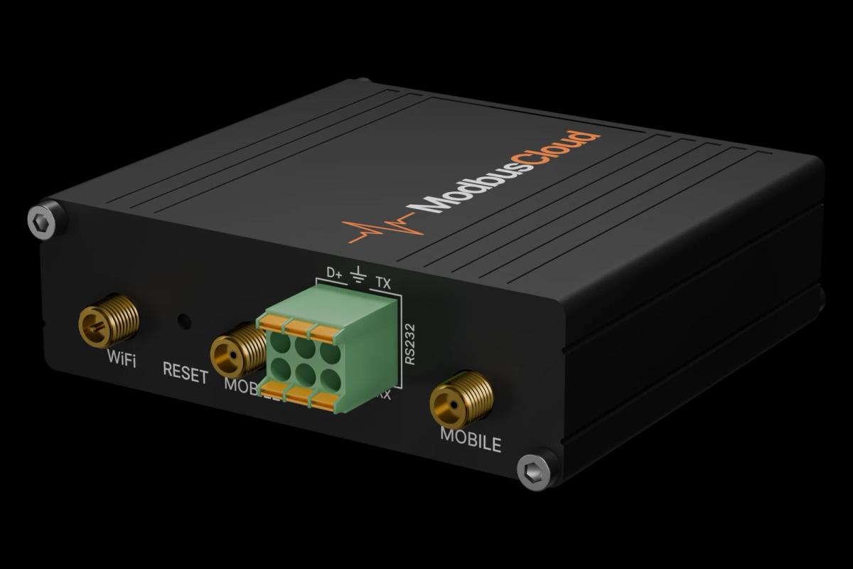
Connect the EIA-485 terminals of the drive to RS485 A, B and GND of the ModbusCloud Gateway and switch on termination at the end of the bus.
On the drive set 58.01 to Modbus RTU, then node address (58.03), baud rate (58.04) and parity (58.05); refresh with 58.06.
Keep 58.33 Addressing mode on Mode 0 and 58.34 Word order on LO-HI, the defaults this template uses.
In ModbusCloud, add a Modbus device (RTU) with the same address and serial settings, then import this template.
Check that motor speed and output frequency follow the drive display while the motor runs.
Things to watch for
The drive does not answer on the bus. What should I check?
Modbus RTU is off from the factory: set 58.01 Protocol enable to Modbus RTU and refresh with 58.06 or reboot. Then compare address, baud rate and parity (default 1, 19.2 kbps, 8 even 1) with ModbusCloud, swap A and B if nothing answers and check the termination at both ends.
The 32-bit values are huge or nonsense. Why?
The template expects word order LO-HI (58.34), the factory setting, and addressing mode 0 (58.33). If someone changed either setting, set them back and refresh with 58.06.
Why can I not find some parameters with an index above 99?
In addressing mode 0 only parameter indexes 1 to 99 have a register address. Parameters such as 05.111 or 06.116 exist only on some versions and need mode 2, which changes every address in the template.
A selection parameter shows a number. What does it mean?
Selection lists come through as their number. Look the number up in the firmware manual under the parameter, for example 1 = In1 Start for 20.01 Ext1 commands.
Is it safe to write parameters from ModbusCloud?
Writing changes the drive configuration directly, including motor data, limits and fault functions. Read the value first, change one parameter at a time and avoid motor and safety settings. The drive only follows fieldbus start and reference when 20.01 and the reference source are set to the embedded fieldbus.



Want to see how it works?