

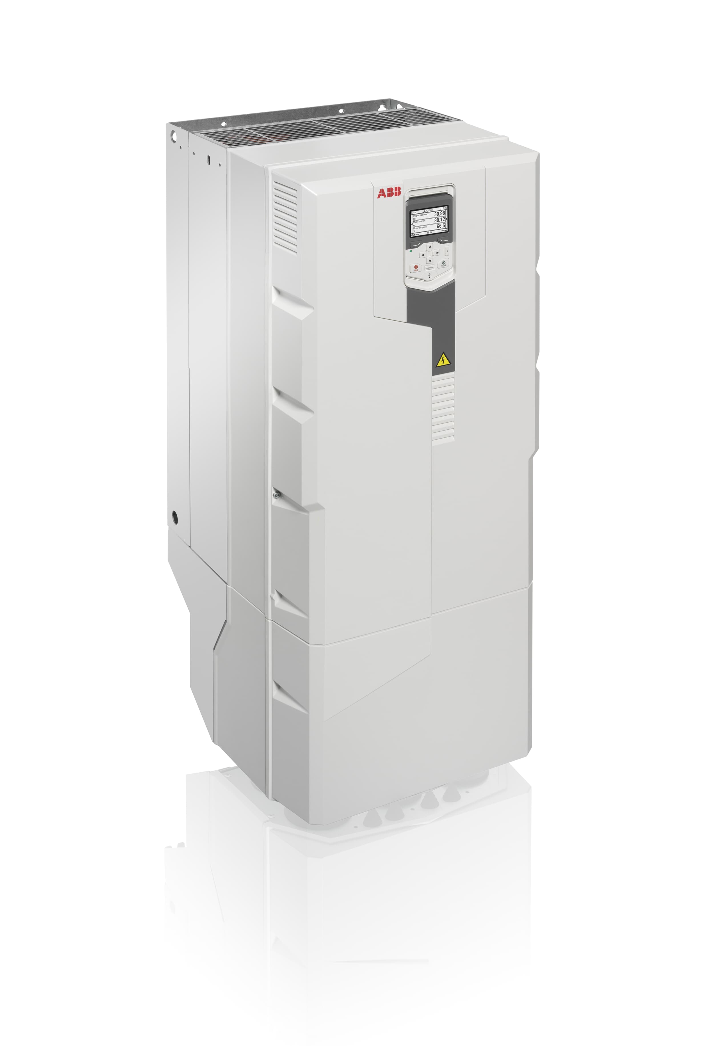
ABB ACS580
ABB
General purpose frequency converter: frequency, current, power, torque, faults and run hours over Modbus RTU on RS485.
Overview
Key readings
- Output frequency and motor speed
- Motor current and output power
- Motor torque
- DC link and output voltage
- Inverter temperature in percent of the fault limit
- Tripping fault and active warning codes
- Energy counters in GWh, MWh and kWh
- Hours run and on-time counter
Use cases
- Alert when Tripping Fault is not equal to 0 and look up the hex code, so a tripped pump or fan drive gets attention right away.
- Track Inverter Temperature against its fault limit of 100 % to spot drives with a blocked heat sink or a hot cabinet.
- Compare Output Frequency and Output Power across pump sets to find a pump that runs harder than its twin.
- Report energy per drive from the Inverter Energy GWh, MWh and kWh counters.
- Plan service from Hours Run and alert on Active Warning before a warning becomes a trip.
Installation
- 1Connect terminal block X5 (EFB) on the control unit to the RS485 A and B of your ModbusCloud Gateway with twisted pair cable. Set TERM to ON at both ends of the bus and BIAS to ON at one device.
- 2On the drive, set 58.01 Protocol enable to Modbus RTU and check 58.03 Node address 1, 58.04 Baud rate 19.2 kbps and 58.05 Parity 8 EVEN 1. Leave 58.33 at Mode 0 and 58.34 at LO-HI, then apply with 58.06 Communication control, Refresh settings.
- 3In ModbusCloud, add a Modbus device (RTU) with address 1, 19200 baud, 8 data bits, even parity and 1 stop bit, and import this template.
- 4Check the link: Output Frequency and Motor Current must match the values on the drive panel. If nothing answers, swap A and B and check 58.01.
Things to watch for
- The drive does not answer on Modbus. What should I check?
- 58.01 Protocol enable must be Modbus RTU, and changes to group 58 only apply after 58.06 Refresh settings or a reboot of the control unit. Check node address, baud rate and parity (default 1, 19.2 kbps, 8 EVEN 1) against ModbusCloud, then swap A and B. Termination must be on at both ends of the bus.
- Values are huge or jump around strangely.
- That is the word order. The template expects the default 58.34 Word order = LO-HI, low word first. If the drive was set to HI-LO, set it back to LO-HI and refresh with 58.06, or the two halves of every 32-bit value are swapped.
- Why does a 16-bit tool show a different frequency?
- The 16-bit register 400106 for 01.06 is scaled to the maximum frequency in 46.02, so its raw value means something else on every drive. The 32-bit register 420212 uses the fixed scale 100 = 1 Hz, which is what this template reads.
- Several drives share one RS485 bus. Anything special?
- Give each drive its own node address in 58.03 and the same baud rate and parity. TERM goes on at the two ends only, BIAS on at one device. The ModbusCloud Gateway must be the only Modbus master on that line.
- Output power reads in the wrong unit.
- Parameter 01.14 follows 96.16 Unit selection. With hp selected the value is in hp, not kW. Set the unit to kW on the drive or read the value as hp; the scale of 0.01 stays the same.
Registers (22)
22 read / 0 write
| Name | Address | Function | Type | Unit | Access |
|---|---|---|---|---|---|
Output Frequency Estimated drive output frequency, 0.01 Hz (FbEq32 100 = 1 Hz), range -500 to 500 Hz. ABB parameter 01.06 Output frequency. | ••• | ••• | ••• | Hz | R |
Motor Current Measured motor current, 0.01 A (FbEq32 100 = 1 A). ABB parameter 01.07 Motor current. | ••• | ••• | ••• | A | R |
Output Power Drive output power, 0.01 (FbEq32 100 = 1 unit). Unit is kW unless parameter 96.16 Unit selection is set to hp. ABB parameter 01.14 Output power. | ••• | ••• | ••• | kW | R |
Motor Torque Motor torque in percent of nominal motor torque, 0.1 % (FbEq32 10 = 1 %), range -1600 to 1600 %. ABB parameter 01.10 Motor torque. | ••• | ••• | ••• | % | R |
DC Voltage Measured DC link voltage, 0.01 V (FbEq32 100 = 1 V). ABB Technical Note 062: readable as 32-bit from firmware 2.15. ABB parameter 01.11 DC voltage. | ••• | ••• | ••• | V | R |
Output Voltage Calculated motor voltage in V AC (FbEq32 1 = 1 V). ABB parameter 01.13 Output voltage. | ••• | ••• | ••• | V | R |
Motor Speed Estimated motor speed, 0.01 rpm (FbEq32 100 = 1 rpm), range -30000 to 30000 rpm. ABB parameter 01.01 Motor speed used. | ••• | ••• | ••• | rpm | R |
Motor Speed Percent Motor speed in percent of synchronous speed, 0.01 % (FbEq32 100 = 1 %). ABB parameter 01.03 Motor speed %. | ••• | ••• | ••• | % | R |
Motor Current Percent Motor current in percent of nominal motor current, 0.1 % (FbEq32 10 = 1 %). ABB parameter 01.08 Motor current % of motor nom. | ••• | ••• | ••• | % | R |
Output Power Percent Output power in percent of nominal motor power, 0.01 % (FbEq32 100 = 1 %), range -300 to 300 %. ABB parameter 01.15 Output power % of motor nom. | ••• | ••• | ••• | % | R |
Inverter Temperature Estimated drive temperature in percent of the fault limit, 0.1 % (FbEq32 10 = 1 %). 0 % = 0 °C, 100 % = fault limit. ABB parameter 05.11 Inverter temperature. | ••• | ••• | ••• | % | R |
Inverter Energy GWh Energy through the drive in full GWh, 0 to 65535 (FbEq32 1 = 1 GWh). Total = GWh x 1000000 + MWh x 1000 + kWh. ABB parameter 01.18 Inverter GWh counter. | ••• | ••• | ••• | R | |
Inverter Energy MWh Energy through the drive, MWh part, 0 to 1000 (FbEq32 1 = 1 MWh). Rolls over into the GWh counter. ABB parameter 01.19 Inverter MWh counter. | ••• | ••• | ••• | MWh | R |
Inverter Energy kWh Energy through the drive, kWh part, 0 to 1000 (FbEq32 1 = 1 kWh). Rolls over into the MWh counter. ABB parameter 01.20 Inverter kWh counter. | ••• | ••• | ••• | kWh | R |
Tripping Fault Code of the 1st active fault, the one that caused the trip, 0000h to FFFFh. 0 = no active fault. Look up the hex code in the fault list of the firmware manual. ABB parameter 04.01 Tripping fault. | ••• | ••• | ••• | R | |
Active Warning Code of the 1st active warning, 0000h to FFFFh. 0 = no active warning. Look up the hex code in the warning list of the firmware manual. ABB parameter 04.06 Active warning 1. | ••• | ••• | ••• | R | |
Latest Fault Code of the 1st stored (no longer active) fault, 0000h to FFFFh. ABB parameter 04.11 Latest fault. | ••• | ••• | ••• | R | |
Main Status Word Main status word as a packed bit field (bit meanings in the parameter description of 06.11). ABB parameter 06.11 Main status word. | ••• | ••• | ••• | R | |
Drive Status Word 1 Drive status word 1 as a packed bit field (bit meanings in the parameter description of 06.16). ABB parameter 06.16 Drive status word 1. | ••• | ••• | ••• | R | |
Hours Run Motor run time in hours, 0.1 h (FbEq32 10 = 1 h): 24 x 05.02 plus the fraction of the current day. ABB parameter 05.03 Hours run. | ••• | ••• | ••• | h | R |
Run Time Days Motor run-time counter in full days, 0 to 65535 d. Runs while the inverter modulates. ABB parameter 05.02 Run-time counter. | ••• | ••• | ••• | d | R |
On Time Days On-time counter in full days, 0 to 65535 d. Runs while the drive is powered. ABB parameter 05.01 On-time counter. | ••• | ••• | ••• | d | R |
Loading registers…
Read the ABB ACS580 remotely
We load the templates onto the gateway and set up your portal, you connect it at your customer's site. Tell us briefly what you need and we'll send a proposal.
From €295 + €149/year.
Prefer to configure it yourself? Order the gateway in the shop·Or see the live demo first
More ABB templates
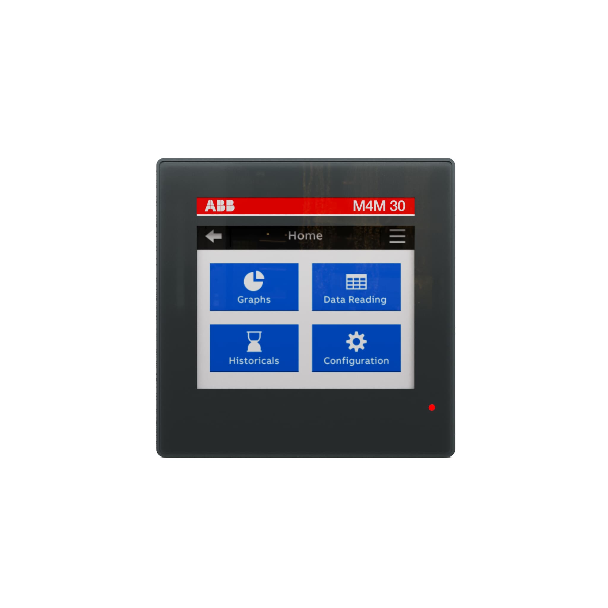
ABB M4M 30
ABB
Network analyzer for switchboards: voltage, current, power, power factor, THD and energy over Modbus RTU on RS485.
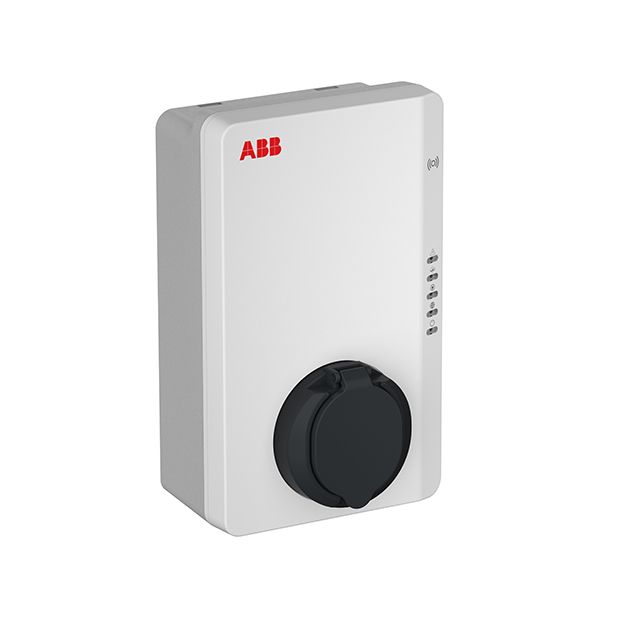
ABB Terra AC
ABB
Monitors and controls ABB Terra AC Wallbox charging via Modbus RTU
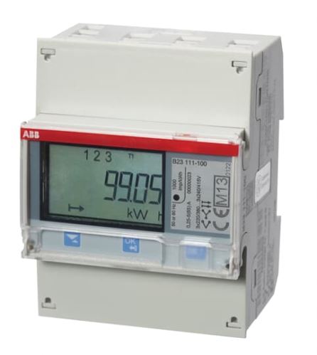
Energy meter ABB B23
ABB
Reads energy values from a 3-phase ABB B23 energy meter via Modbus RTU.
More RTU templates

Alnor HRU
Alnor Systemy Wentylacji Sp. z o. o.
Controls and monitors Alnor heat recovery ventilation units via Modbus RTU.

connecdoor.controller
connecdoor
Controls and monitors smart door access points via RS485
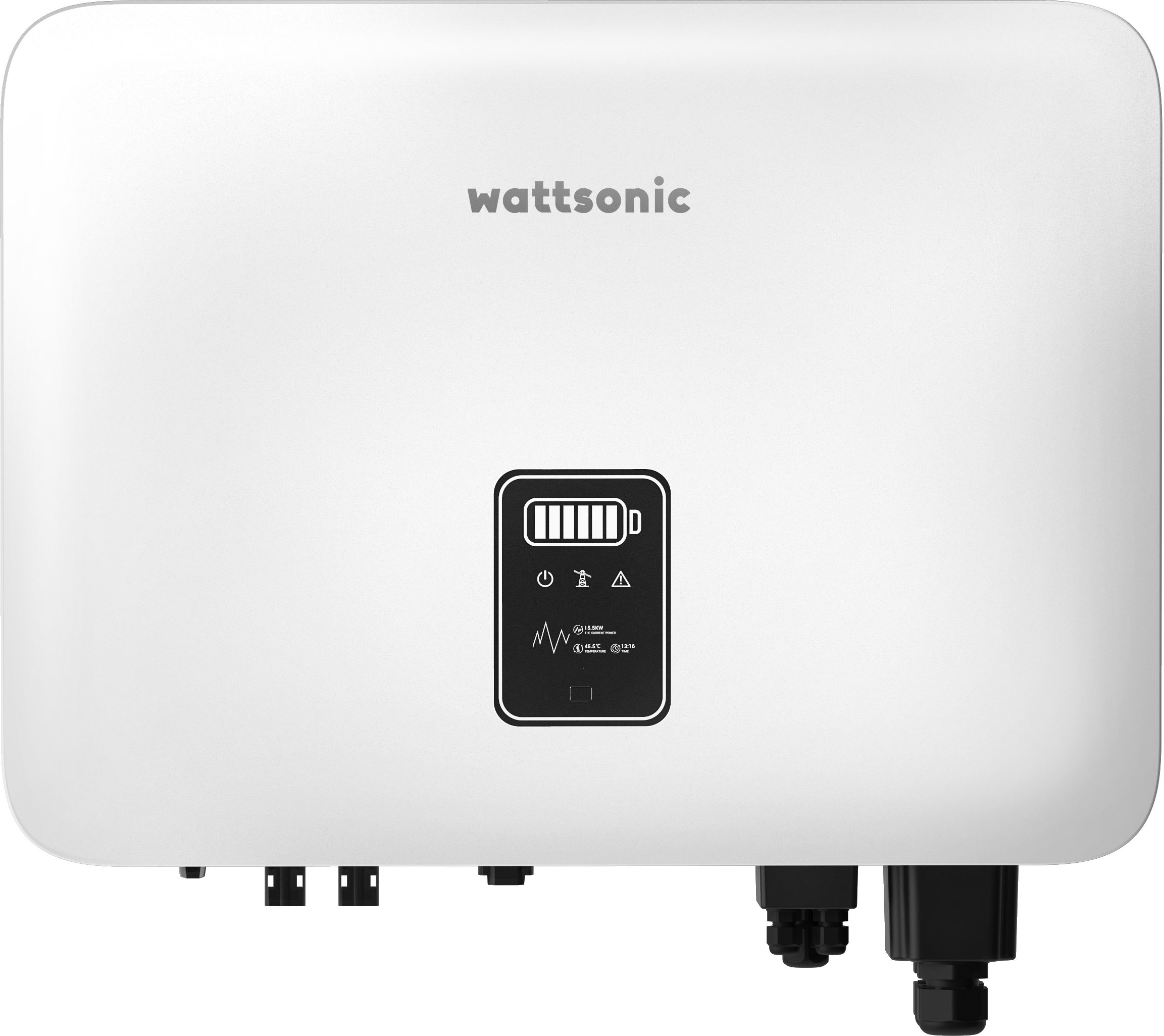
Wattsonic - Schmachtl Sun Energy Box
Wattsonic
Monitors Schmachtl Wattsonic hybrid inverter via Modbus RTU

Alnor HRU-P
Alnor Systemy Wentylacji Sp. z o. o.
Controls Alnor HRU-P heat recovery ventilation units via Modbus RTU.

Heidelberg Wallbox Energy Control
AMPERFIED GmbH
Controls and monitors Heidelberg Wallbox Energy Control EV charger via Modbus RTU.
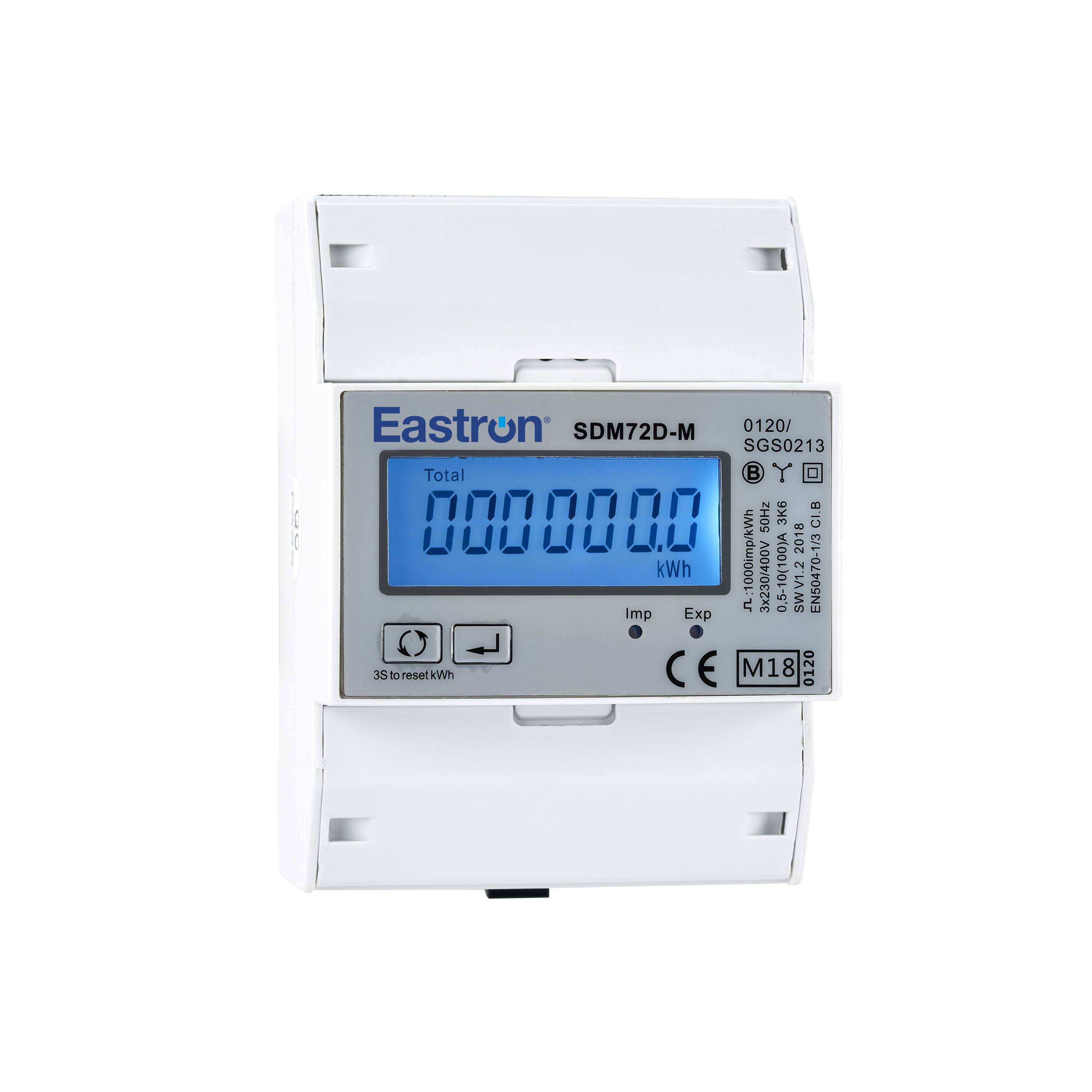
Eastron SDM72D-M
Eastron
Reads energy metering values from an Eastron SDM72D-M three-phase meter.