

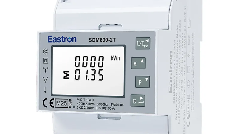
ABB Tmax XT Ekip Touch
Moulded case circuit breaker with breaker status, currents, voltages, power and energy.
The ABB Tmax XT is a moulded case circuit breaker that protects and measures feeders in main and sub-distribution boards, with the Ekip Touch trip unit doing the measuring. This Modbus RTU template reads breaker status, trips, currents, voltages, power, energy and contact wear, and lets you send commands and set the clock from ModbusCloud.
- Protocol
- Modbus RTU
- Connection
- RS485, 19200 baud
- Registers
- 267, read and write
- Brand
- ABB
- Key readings
- Breaker status · Phase currents · Line voltages · Active power · Power factor · Frequency · Active energy · Contact wear
- Available commands
- Breaker commands · Trip reset · Clock
- Compatible models
- Tmax XT2 · Tmax XT4 · Tmax XT5 · Tmax XT7 · Ekip Com Modbus RTU · Ekip Com Modbus TCP
- Last updated
Registers (267)
267 read, 4 write
| Name | Unit | Access | Address (Hidden until you enter your email) | Function (hidden) | Type (hidden) |
|---|---|---|---|---|---|
| Command (type+parameter) | Read and write | 0 | FC03 / FC16 | uint32 | |
| Seconds Low | s | Read and write | 3 | FC03 / FC06 | uint16 |
| Seconds High | s | Read and write | 4 | FC03 / FC06 | uint16 |
| Milliseconds | ms | Read and write | 5 | FC03 / FC06 | uint16 |
| Contact Wear | % | Read | 20 | FC04 | uint16 |
| Nr of CB operations | Read | ||||
| Nr of CB manual openings | Read | ||||
| Nr of CB protection trips | Read | ||||
| Nr of CB protection trip fails | Read | ||||
| Nr of CB protection trip test | Read | ||||
| Programming Fail error code | Read | ||||
| Status Global 1 | Read | ||||
| Status Global 2 | Read | ||||
| Status Glitch 1 | Read | ||||
| Status Glitch 2 | Read | ||||
| Status Flags 1 | Read | ||||
| Status Flags 2 | Read | ||||
| Status Accessories 1 | Read | ||||
| Status Accessories 2 | Read | ||||
| Status Timing 1 | Read | ||||
| Status Timing 2 | Read | ||||
| Status Trips 1 (Latched) | Read | ||||
| Status Trips 2 (Latched) | Read | ||||
| Status Trips 3 (Latched) | Read | ||||
| Status Warnings Alarms 1 | Read | ||||
| Status Warnings Alarms 2 | Read | ||||
| Status Warnings Alarms 3 | Read | ||||
| Status Warnings Alarms 4 | Read | ||||
| Status Warnings Alarms 5 | Read | ||||
| Status Warnings Alarms 6 | Read | ||||
| Status Ekip Signalling 1K / Maintenance Module + Local I/O | Read | ||||
| Status Ekip Signalling 10K input A | Read | ||||
| Status Ekip Signalling 10K input B | Read | ||||
| Status Ekip Signalling 2K input | Read | ||||
| Status Ekip Signalling 10K output A | Read | ||||
| Status Ekip Signalling 10K output B | Read | ||||
| Status Ekip Signalling 2K output | Read | ||||
| Spare | Read | ||||
| Programmable Status | Read | ||||
| Ekip Link Actors Status | Read | ||||
| Load Output Status | Read | ||||
| Status ZS IN Remote | Read | ||||
| Status ZS OUT Remote | Read | ||||
| Accessories3 | Read | ||||
| Remote Programmable Status Bits | Read | ||||
| Remote Actor Selected Status Register A | Read | ||||
| Remote Actor Selected Status Register B | Read | ||||
| Remote Actor Selected Status Register C | Read | ||||
| Remote Actor Selected Status Register D | Read | ||||
| Zone Selectivity Protection Status | Read | ||||
| Ekip Signalling 3T 1 Protection Status | Read | ||||
| Status Flags 3 | Read | ||||
| Status Warnings Alarms 7 | Read | ||||
| Status Warnings Alarms 8 | Read | ||||
| Status Timing 3 | Read | ||||
| Status Timing 4 | Read | ||||
| Status Trips 4 (Latched) | Read | ||||
| PLC output | Read | ||||
| PLC output 2 | Read | ||||
| L1 current | A | Read | |||
| L2 current | A | Read | |||
| L3 current | A | Read | |||
| Ne current | A | Read | |||
| Internal ground current | A | Read | |||
| External ground current/Rc current | A | Read | |||
| Maximum current | Read | ||||
| Maximum current phase | Read | ||||
| L1 min Current Value | Read | ||||
| Timestamp of L1 Min Current [s] | Read | ||||
| L1 max Current Value | Read | ||||
| Timestamp of L1 Max Current [s] | Read | ||||
| L2 min Current Value | Read | ||||
| Timestamp of L2 Min Current [s] | Read | ||||
| L2 max Current Value | Read | ||||
| Timestamp of L2 Max Current [s] | Read | ||||
| L3 min Current Value | Read | ||||
| Timestamp of L3 Min Current [s] | Read | ||||
| L3 max Current Value | Read | ||||
| Timestamp of L3 Max Current [s] | Read | ||||
| Ne min Current Value | Read | ||||
| Timestamp of Ne Min Current [s] | Read | ||||
| Ne max Current Value | Read | ||||
| Timestamp of Ne Max Current [s] | Read | ||||
| V1 line to neutral voltage | V | Read | |||
| V2 line to neutral voltage | V | Read | |||
| V3 line to neutral voltage | V | Read | |||
| V0 residual voltage | V | Read | |||
| V12 line to line voltage | V | Read | |||
| V23 line to line voltage | V | Read | |||
| V31 line to line voltage | V | Read | |||
| Vxy Maximum voltage | V | Read | |||
| Vxy Maximum voltage phase | Read | ||||
| Min Voltage Value | Read | ||||
| Min Voltage Phase | Read | ||||
| Timestamp of Min Voltage Seconds Low | Read | ||||
| Timestamp of Min Voltage Seconds High | Read | ||||
| Max Voltage Value | Read | ||||
| Max Voltage Phase | Read | ||||
| Timestamp of Max Voltage Seconds Low | Read | ||||
| Timestamp of Max Voltage Seconds High | Read | ||||
| L1 current (Float) | A | Read | |||
| L2 current (Float) | A | Read | |||
| L3 current (Float) | A | Read | |||
| Ne current (Float) | A | Read | |||
| Power Factor L1 (Float) | Read | ||||
| Power Factor L2 (Float) | Read | ||||
| Power Factor L3 (Float) | Read | ||||
| Power Factor Total (Float) | Read | ||||
| V1 voltage (Float) | V | Read | |||
| V2 voltage (Float) | V | Read | |||
| V3 voltage (Float) | V | Read | |||
| V12 voltage (Float) | V | Read | |||
| V23 voltage (Float) | V | Read | |||
| V31 voltage (Float) | V | Read | |||
| Active power L1 | kW | Read | |||
| Active power L2 | kW | Read | |||
| Active power L3 | kW | Read | |||
| Active power Total | kW | Read | |||
| Reactive power L1 | kvar | Read | |||
| Reactive power L2 | kvar | Read | |||
| Reactive power L3 | kvar | Read | |||
| Reactive power Total | kvar | Read | |||
| Apparent power L1 | kVA | Read | |||
| Apparent power L2 | kVA | Read | |||
| Apparent power L3 | kVA | Read | |||
| Apparent power Total | kVA | Read | |||
| Active power L1 (Float) | kW | Read | |||
| Active power L2 (Float) | Read | ||||
| Active power L3 (Float) | Read | ||||
| Active power Total (Float) | Read | ||||
| Reactive power L1 (Float) | kvar | Read | |||
| Reactive power L2 (Float) | Read | ||||
| Reactive power L3 (Float) | Read | ||||
| Reactive power Total (Float) | Read | ||||
| Apparent power L1 (Float) | kVA | Read | |||
| Apparent power L2 (Float) | Read | ||||
| Apparent power L3 (Float) | Read | ||||
| Apparent power Total (Float) | Read | ||||
| Power Factor L1 | Read | ||||
| Power Factor L2 | Read | ||||
| Power Factor L3 | Read | ||||
| Power Factor Total | Read | ||||
| Frequency | Hz | Read | |||
| Peak Factor L1 | Read | ||||
| Peak Factor L2 | Read | ||||
| Peak Factor L3 | Read | ||||
| Peak Factor Ne | Read | ||||
| 3 secs Average Value Positive Sequence | V | Read | |||
| 3 secs Average Value Negative Sequence | V | Read | |||
| 3 secs Average Value Unbalance | % | Read | |||
| L1 THD | % | Read | |||
| L2 THD | % | Read | |||
| L3 THD | % | Read | |||
| Ne THD | % | Read | |||
| V12 THD | % | Read | |||
| V23 THD | % | Read | |||
| V31 THD | % | Read | |||
| loadProfile 0-49% In | s | Read | |||
| loadProfile 50-79% In | s | Read | |||
| loadProfile 79-89% In | s | Read | |||
| loadProfile 90% In | s | Read | |||
| Active Energy Positive | kWh | Read | |||
| Active Energy Negative | kWh | Read | |||
| Active Energy Total | kWh | Read | |||
| Reactive Energy Positive | kvarh | Read | |||
| Reactive Energy Negative | kvarh | Read | |||
| Reactive Energy Total | kvarh | Read | |||
| Apparent Energy Total | kVAh | Read | |||
| Energy Store Time | s | Read | |||
| Active Energy Total (Float) | kWh | Read | |||
| Reactive Energy Total (Float) | Read | ||||
| Apparent Energy Total (Float) | Read | ||||
| Total Harmonic Distortion (THD) | % | Read | |||
| 1th harmonic ratio | % | Read | |||
| 2th harmonic ratio | % | Read | |||
| 3th harmonic ratio | % | Read | |||
| 4th harmonic ratio | % | Read | |||
| 5th harmonic ratio | % | Read | |||
| 6th harmonic ratio | % | Read | |||
| 7th harmonic ratio | % | Read | |||
| 8th harmonic ratio | % | Read | |||
| 9th harmonic ratio | % | Read | |||
| 10th harmonic ratio | % | Read | |||
| 11th harmonic ratio | % | Read | |||
| 12th harmonic ratio | % | Read | |||
| 13th harmonic ratio | % | Read | |||
| 14th harmonic ratio | % | Read | |||
| 15th harmonic ratio | % | Read | |||
| 16th harmonic ratio | % | Read | |||
| 17th harmonic ratio | % | Read | |||
| 18th harmonic ratio | % | Read | |||
| 19th harmonic ratio | % | Read | |||
| 20th harmonic ratio | % | Read | |||
| 21st harmonic ratio | % | Read | |||
| 22nd harmonic ratio | % | Read | |||
| 23rd harmonic ratio | % | Read | |||
| 24th harmonic ratio | % | Read | |||
| 25th harmonic ratio | % | Read | |||
| 26th harmonic ratio | % | Read | |||
| 27th harmonic ratio | % | Read | |||
| 28th harmonic ratio | % | Read | |||
| 29th harmonic ratio | % | Read | |||
| 30th harmonic ratio | % | Read | |||
| 31st harmonic ratio | % | Read | |||
| 32nd harmonic ratio | % | Read | |||
| 33rd harmonic ratio | % | Read | |||
| 34th harmonic ratio | % | Read | |||
| 35th harmonic ratio | % | Read | |||
| 36th harmonic ratio | % | Read | |||
| 37th harmonic ratio | % | Read | |||
| 38th harmonic ratio | % | Read | |||
| 39th harmonic ratio | % | Read | |||
| 40th harmonic ratio | % | Read | |||
| 41st harmonic ratio | % | Read | |||
| 42nd harmonic ratio | % | Read | |||
| 43rd harmonic ratio | % | Read | |||
| 44th harmonic ratio | % | Read | |||
| 45th harmonic ratio | % | Read | |||
| 46th harmonic ratio | % | Read | |||
| 47th harmonic ratio | % | Read | |||
| 48th harmonic ratio | % | Read | |||
| 49th harmonic ratio | % | Read | |||
| 50th harmonic ratio | % | Read | |||
| Channel Number | Read | ||||
| Slave ID | Read | ||||
| Core SW version | Read | ||||
| Product Standard Reference | Read | ||||
| CB flags | Read | ||||
| Nominal current | A | Read | |||
| Information Flags | Read | ||||
| CB serial number | Read | ||||
| CB Name | Read | ||||
| Nr of CB Poles | Read | ||||
| Ekip Type | Read | ||||
| Relay SW version | Read | ||||
| Relay serial number | Read | ||||
| Neutral Selection | Read | ||||
| Net Frequency | Read | ||||
| Product Execution | Read | ||||
| Core serial number | Read | ||||
| Unit configuration | Read | ||||
| Date Of CB Last Maintenance Seconds Low | s | Read | |||
| Date Of CB Last Maintenance Seconds High | s | Read | |||
| Datalogger Status | Read | ||||
| DLog 1 Trigger Type | Read | ||||
| DLog 1 Trigger Timestamp Seconds Low | Read | ||||
| DLog 1 Trigger Timestamp Seconds High | Read | ||||
| DLog 1 Trigger Timestamp Milliseconds | Read | ||||
| DLog 1 Max File | Read | ||||
| DLog 1 Max Addr | Read | ||||
| DLog 2 Trigger Type | Read | ||||
| DLog 2 Trigger Timestamp Seconds Low | Read | ||||
| DLog 2 Trigger Timestamp Seconds High | Read | ||||
| DLog 2 Trigger Timestamp Milliseconds | Read | ||||
| DLog 2 Max File | Read | ||||
| DLog 2 Max Addr | Read | ||||
| Register 560 | Read | ||||
| Installed Measuring Module serial number | Read | ||||
| Protections Enabled 1 | Read | ||||
| Protections Enabled 2 | Read | ||||
| Protections Enabled 3 | Read | ||||
| Protections Enabled 4 | Read | ||||
| Protections Enabled 5 | Read | ||||
| Protections Enabled 6 | Read | ||||
| Protections Enabled 7 | Read | ||||
| Protections Enabled 8 | Read | ||||
| Device Name | Read |
Loading registers…
Send your device list
If a device is not in the library yet, we build the template for free as soon as we have the register data.
Use cases
- See on one dashboard which breakers in a switchboard are closed, open or tripped.
- Get an alert when the status shows a trip, alarm or warning, so you know about a fault before the customer calls.
- Track the load per feeder over months with current, power and energy history.
- Plan maintenance from the contact wear and the number of trips per breaker.
- Watch THD and power factor on feeders with drives or other non-linear loads.
Installation
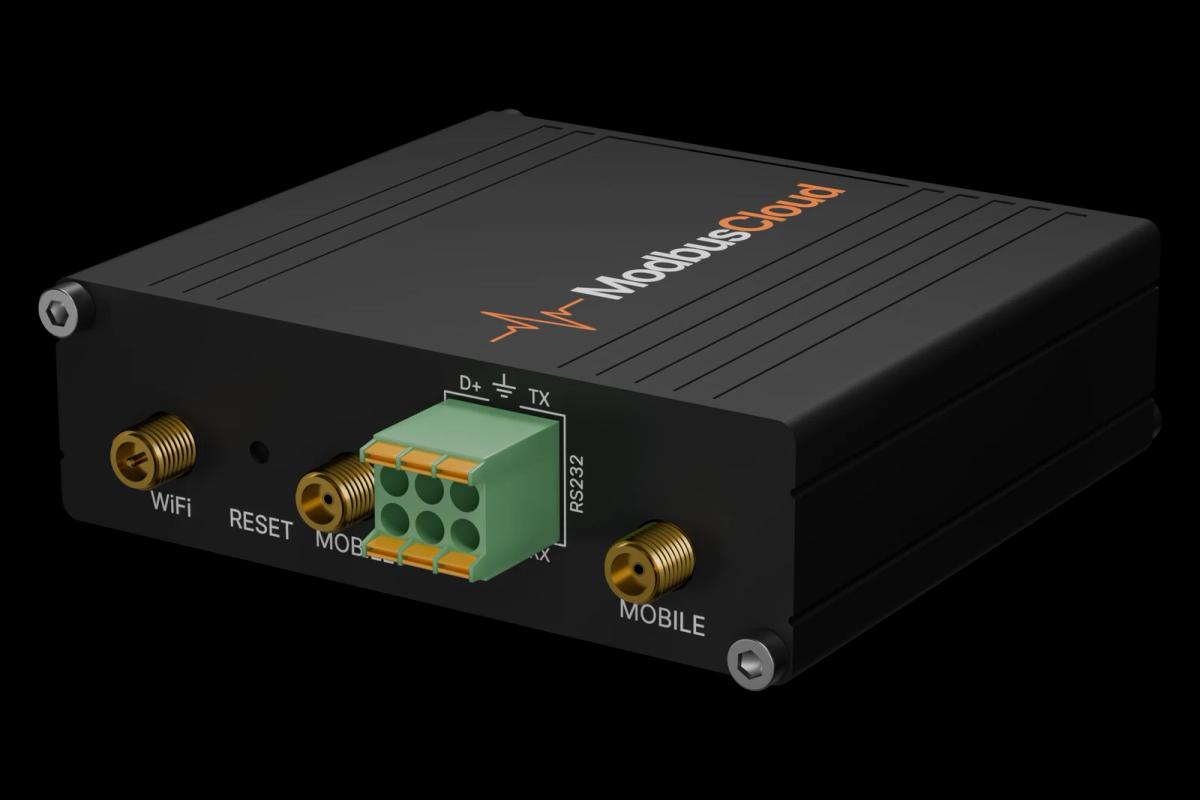
Fit an Ekip Com Modbus RTU module to the Tmax XT and connect A and B to the RS485 port of the ModbusCloud Gateway, with termination at both ends of the bus.
Set a unique Modbus address on each trip unit; the default is 247 at 19200 baud, even parity, 8 data bits, 1 stop bit.
In ModbusCloud, add a Modbus device on the Gateway, import the ABB Tmax XT Ekip Touch template and enter address and serial settings.
Check that the breaker status and the phase currents come in and match the trip unit display.
Things to watch for
The trip unit does not answer on the bus. What should I check?
Check the Ekip Com address, speed and parity against the device settings in ModbusCloud; the default is 247 at 19200 baud, even parity. Swap A and B if nothing answers, and check that the breaker is racked in, as only the connection status is valid when the trip unit is disconnected.
Why do current and energy values look far too large?
The 32-bit values are sent with the low word first. The template already reads them that way; if you copied registers into your own template, set the word order to low word first.
Some registers return 65535 or a maximum value. Is the breaker faulty?
No. The trip unit uses the highest value of the data type for a measure that is not available, for example voltages without a voltage module or the external ground current on frames other than XT7.
What should I know before writing a command?
Commands such as open, close and trip reset act on a live breaker. Only write them when the installation and the customer allow it, and check that the trip unit is set to remote. Settings outside the command register need a programming session, which this template does not cover.



Want to see how it works?