

Danfoss AK-CC25 Pro
Case and cold room controller: temperatures, compressor, defrost, fans and alarms.
The Danfoss AK-CC25 Pro is a controller for refrigerated display cases and cold rooms that runs the compressor, defrost, evaporator fans, light and rail heat. This Modbus RTU template reads air, evaporator and product temperatures, control state, outputs and alarms, and lets you write the main switch, cut-out, alarm limits and defrost commands from ModbusCloud.
- Protocol
- Modbus RTU
- Connection
- RS485, 19200 baud
- Registers
- 277, read and write
- Brand
- Danfoss
- Key readings
- Thermostat air temperature · Evaporator temperature · Product temperature · Control state · Compressor and fan status · Alarms
- Available commands
- Main switch · Cut-out temperature · Alarm limits · Defrost start and stop · Alarm reset
- Compatible models
- AK-CC25 Pro 084B4022 · AK-CC25 Pro 084B4023
- Last updated
Registers (277)
277 read, 203 write
| Name | Unit | Access | Address (Hidden until you enter your email) | Function (hidden) | Type (hidden) |
|---|---|---|---|---|---|
| Thermostat Air Temp. | °C | Read | |||
| Display Readout Temperature | °C | Read | |||
| Alarm Air Temp. | °C | Read | |||
| S3 Air ON Evap. | °C | Read | |||
| S4 Air OFF Evap. | °C | Read | |||
| S5 Evaporator A | °C | Read | |||
| S5 Evaporator B | °C | Read | |||
| S6 Product Temp. | °C | Read | |||
| Food Temperature | °C | Read | |||
| Defrost Sensor Temp. A | °C | Read | |||
| Defrost Sensor Temp. B | °C | Read | |||
| Sc Condenser Temp. | °C | Read | |||
| Control State | Read | ||||
| Alarm Status | Read | ||||
| Actual High Alarm Limit | °C | Read | |||
| Actual Low Alarm Limit | °C | Read | |||
| Compressor 1 | Read | ||||
| Compressor 2 | Read | ||||
| Fan | Read | ||||
| Defrost A | Read | ||||
| Defrost B | Read | ||||
| Rail Heat | Read | ||||
| Alarm Relay | Read | ||||
| Light | Read | ||||
| Condenser Fan | Read | ||||
| Compressor Speed | % | Read | |||
| DI1 Status | Read | ||||
| DI2 Status | Read | ||||
| Night Condition | Read | ||||
| Defrost Time | min | Read | |||
| Thermostat Run Time | min | Read | |||
| Thermostat Cut-in Temp. | °C | Read | |||
| Thermostat Cut-out Temp. | °C | Read | |||
| Drip Tray Heater | Read | ||||
| Air Heater | Read | ||||
| Rail Heat Power | % | Read | |||
| Network Status | % | Read | |||
| Operation Mode | Read | ||||
| Hardware Failure | Read | ||||
| Clock Lost Time | Read | ||||
| S3 Air ON Evap. A Sensor Error | Read | ||||
| S4 Air OFF Evap. A Sensor Error | Read | ||||
| S5 Evaporator A Sensor Error | Read | ||||
| S6 Product Temp. A Sensor Error | Read | ||||
| S5 Evaporator B Sensor Error | Read | ||||
| Sc Condenser Temp. Sensor Error | Read | ||||
| High Temperature Alarm A | Read | ||||
| Low Temperature Alarm A | Read | ||||
| Door Open Alarm | Read | ||||
| Max Defrost Hold Time Exceeded | Read | ||||
| DI Alarm 1 | Read | ||||
| DI Alarm 2 | Read | ||||
| Comp. Safety 1 | Read | ||||
| Main Switch Set OFF | Read | ||||
| Case In Cleaning Mode | Read | ||||
| Cond. High Temperature | Read | ||||
| Cond. Block Alarm | Read | ||||
| Refrigerant Leak Detected | Read | ||||
| Wrong IO Configuration | Read | ||||
| Max Defrost Time Exceeded A | Read | ||||
| Comp. Safety 2 | Read | ||||
| Comp. Safety Lockout | Read | ||||
| Main Switch | Read and write | ||||
| Start Defrost | Read and write | ||||
| Stop Defrost | Read and write | ||||
| Reset Alarms | Read and write | ||||
| Mute Alarm | Read and write | ||||
| Cut-out 1 | °C | Read and write | |||
| Night Offset | °C | Read and write | |||
| High Alarm Limit | °C | Read and write | |||
| Low Alarm Limit | °C | Read and write | |||
| Thermostat Mode | Read | ||||
| DO1 Function | Read | ||||
| DO2 Function | Read | ||||
| DO3 Function | Read | ||||
| DO4 Function | Read | ||||
| AO1 Function | Read | ||||
| DI1 Function | Read | ||||
| DI2 Function | Read | ||||
| AI1 Function | Read | ||||
| AI2 Function | Read | ||||
| AI3 Function | Read | ||||
| AI4 Function | Read | ||||
| Differential | °C | Read and write | |||
| Max Cut-out Limit | °C | Read and write | |||
| Min Cut-out Limit | °C | Read and write | |||
| Display Readout Adjustment | °C | Read and write | |||
| Temperature Unit | Read and write | ||||
| S4 Air OFF Evap. Adjustment | °C | Read and write | |||
| S3 Air ON Evap. Adjustment | °C | Read and write | |||
| S5 Evaporator Adjustment | °C | Read and write | |||
| Melt Period | min | Read and write | |||
| Melt Interval | h | Read and write | |||
| Thermostat Sensor S4 % | % | Read and write | |||
| S6 Product Temp. Adjustment | °C | Read and write | |||
| Thermostat Sensor S4 % Night | % | Read and write | |||
| Air Heater Neutral Zone | °C | Read and write | |||
| Air Heater Start Delay | min | Read and write | |||
| Food Type | Read and write | ||||
| S4 Frost Protection | °C | Read and write | |||
| Temp. Pulldown Diff | °C | Read and write | |||
| Temp. Pulldown Time | min | Read and write | |||
| Min ON Time | min | Read and write | |||
| Min OFF Time | min | Read and write | |||
| Delay Between Comp. | s | Read and write | |||
| Step Control Mode | Read and write | ||||
| Speed Kp | Read and write | ||||
| Speed Tn | s | Read and write | |||
| Minimum Speed | Hz | Read and write | |||
| Start Speed | Hz | Read and write | |||
| Max Speed | Hz | Read and write | |||
| Max Speed Slope | Read and write | ||||
| Comp. Defrost Speed | % | Read and write | |||
| Max. Kp Factor | Read and write | ||||
| Comp Cut-out Delay | s | Read and write | |||
| Stop Speed | Hz | Read and write | |||
| Defrost Method | Read and write | ||||
| Defrost Stop Limit | °C | Read and write | |||
| Defrost Start Interval | h | Read and write | |||
| Max. Defrost Time | min | Read and write | |||
| Time Staggering Power-up | min | Read and write | |||
| Drip Off Time | min | Read and write | |||
| Fan Start Temperature | °C | Read and write | |||
| Fan Start Delay | min | Read and write | |||
| Fan Control During Defrost | Read and write | ||||
| Defrost Stop Method | Read and write | ||||
| Pump Down Delay | min | Read and write | |||
| Max. Thermostat Run Time | h | Read and write | |||
| DOD S5 Differential | °C | Read and write | |||
| Drip Tray Heater Delay | min | Read and write | |||
| Min. Defrost Time | min | Read and write | |||
| Rail Heat During Defrost | Read and write | ||||
| Display Delay After Defrost | min | Read and write | |||
| Fan Stop Temperature | °C | Read and write | |||
| Pressure Equalization Delay | min | Read and write | |||
| Hot Gas Valve At Drip | Read and write | ||||
| Temp. Pulldown After Defrost | Read and write | ||||
| Defrost Schedule | Read and write | ||||
| Def. Start 1 Hours | h | Read and write | |||
| Def. Start 2 Hours | h | Read and write | |||
| Def. Start 3 Hours | h | Read and write | |||
| Def. Start 4 Hours | h | Read and write | |||
| Def. Start 5 Hours | h | Read and write | |||
| Def. Start 6 Hours | h | Read and write | |||
| Def. Start 1 Minutes | min | Read and write | |||
| Def. Start 2 Minutes | min | Read and write | |||
| Def. Start 3 Minutes | min | Read and write | |||
| Def. Start 4 Minutes | min | Read and write | |||
| Def. Start 5 Minutes | min | Read and write | |||
| Def. Start 6 Minutes | min | Read and write | |||
| Monday Follow Schedule | Read and write | ||||
| Tuesday Follow Schedule | Read and write | ||||
| Wednesday Follow Schedule | Read and write | ||||
| Thursday Follow Schedule | Read and write | ||||
| Friday Follow Schedule | Read and write | ||||
| Saturday Follow Schedule | Read and write | ||||
| Sunday Follow Schedule | Read and write | ||||
| Event 1 Day H | h | Read and write | |||
| Event 1 Day Min | min | Read and write | |||
| Event 1 Night H | h | Read and write | |||
| Event 1 Night Min | min | Read and write | |||
| Event 2 Day H | h | Read and write | |||
| Event 2 Day Min | min | Read and write | |||
| Event 2 Night H | h | Read and write | |||
| Event 2 Night Min | min | Read and write | |||
| Monday Event | Read and write | ||||
| Tuesday Event | Read and write | ||||
| Wednesday Event | Read and write | ||||
| Thursday Event | Read and write | ||||
| Friday Event | Read and write | ||||
| Saturday Event | Read and write | ||||
| Sunday Event | Read and write | ||||
| Fan Stop High S5 Temp. | °C | Read and write | |||
| Fan Pulsing Mode | Read and write | ||||
| Fan Period Time | min | Read and write | |||
| Fan ON Cycle | % | Read and write | |||
| Cond. Fan Cut-in | °C | Read and write | |||
| Cond. Fan Diff. | °C | Read and write | |||
| Delay Of Outputs At Power-up | s | Read and write | |||
| DI1 Configuration | Read and write | ||||
| Network Address | Read and write | ||||
| Access Code 3 | Read and write | ||||
| Temperature Sensor Type | Read and write | ||||
| Max. Hold Time | min | Read and write | |||
| Display Air S4% | % | Read and write | |||
| DI2 Configuration | Read and write | ||||
| Case Cleaning Mode | Read and write | ||||
| Light Control Mode | Read and write | ||||
| MC Light Signal | Read and write | ||||
| Rail Heat ON Cycle Day | % | Read and write | |||
| Rail Heat ON Cycle Night | % | Read and write | |||
| Rail Heat Period Time | min | Read and write | |||
| Application Mode | Read and write | ||||
| Access Code 2 | Read and write | ||||
| Drip Tray Heater Override | Read and write | ||||
| Rail Heat Control Mode | Read and write | ||||
| Dewpoint Min. Limit | °C | Read and write | |||
| Dewpoint Max. Limit | °C | Read and write | |||
| Rail Heat Min. ON Cycle | % | Read and write | |||
| Door Restart Inj. Delay | min | Read and write | |||
| Display Readout | Read and write | ||||
| Light At Main Switch OFF | Read and write | ||||
| Alarm Relay Priority | Read and write | ||||
| Fan Stop At Blinds Closing | s | Read and write | |||
| Oil Return Speed Limit | % | Read and write | |||
| Oil Return Interval | min | Read and write | |||
| Oil Return Speed | % | Read and write | |||
| Oil Return Time Period | s | Read and write | |||
| DO1 Configuration | Read and write | ||||
| DO2 Configuration | Read and write | ||||
| DO3 Configuration | Read and write | ||||
| DO4 Configuration | Read and write | ||||
| AO1 Configuration | Read and write | ||||
| Compressor 1 Override | Read and write | ||||
| Fan Override | Read and write | ||||
| Defrost A Override | Read and write | ||||
| Rail Heat Override | Read and write | ||||
| Alarm Relay Override | Read and write | ||||
| Light Override | Read and write | ||||
| Compressor 2 Override | Read and write | ||||
| Defrost B Override | Read and write | ||||
| Air Heater Override | Read and write | ||||
| High Temperature Priority | Read and write | ||||
| Low Temperature Priority | Read and write | ||||
| Sensor Errors Priority | Read and write | ||||
| DI Alarms Priority | Read and write | ||||
| Defrost Priority | Read and write | ||||
| Miscellaneous Priority | Read and write | ||||
| Control Stopped Priority | Read and write | ||||
| Leak Detection Priority | Read and write | ||||
| Food Temp. Sensor | Read and write | ||||
| Baudrate | Read and write | ||||
| Parity And Stop Bit | Read and write | ||||
| Safety Action | Read and write | ||||
| Safety Event Period | h | Read and write | |||
| Max Safety Events | Read and write | ||||
| Condenser Fan Override | Read and write | ||||
| Compressor Speed Override | % | Read and write | |||
| Resonance Band Start | % | Read and write | |||
| Resonance Band | % | Read and write | |||
| Compressor Priority | Read and write | ||||
| Condenser Priority | Read and write | ||||
| Sensor Point 1 Temp. | °C | Read and write | |||
| Sensor Point 1 kohm | Read and write | ||||
| Sensor Point 1 ohm | Ω | Read and write | |||
| Sensor Point 2 Temp. | °C | Read and write | |||
| Sensor Point 2 kohm | Read and write | ||||
| Sensor Point 2 ohm | Ω | Read and write | |||
| Sensor Point 3 Temp. | °C | Read and write | |||
| Sensor Point 3 kohm | Read and write | ||||
| Sensor Point 3 ohm | Ω | Read and write | |||
| Access Code 1 | Read and write | ||||
| Display Keyboard Lock | Read and write | ||||
| Manage Operation Mode | Read and write | ||||
| Cond. Fan At Defrost | Read and write | ||||
| Leak Alarm Action | Read and write | ||||
| AI1 Configuration | Read and write | ||||
| AI2 Configuration | Read and write | ||||
| AI3 Configuration | Read and write | ||||
| AI4 Configuration | Read and write | ||||
| Display Filter Time | s | Read and write | |||
| BLE Access Level | Read and write | ||||
| Alarm Delay | min | Read and write | |||
| Door Open Alarm Delay | min | Read and write | |||
| Alarm Delay Pull Down | min | Read and write | |||
| Alarm Delay DI 1 | min | Read and write | |||
| Alarm Delay DI 2 | min | Read and write | |||
| Alarm Sensor S4% | % | Read and write | |||
| Cond. Alarm Limit | °C | Read and write | |||
| Cond. Block Limit | °C | Read and write | |||
| Cond. Alarm Delay | min | Read and write | |||
| Cond. Alarm Differential | °C | Read and write | |||
| Time Hours | h | Read and write | |||
| Time Minutes | min | Read and write | |||
| Time Date | Read and write | ||||
| Time Month | Read and write | ||||
| Time Year | Read and write |
Loading registers…
Send your device list
If a device is not in the library yet, we build the template for free as soon as we have the register data.
Use cases
- Show air, evaporator and product temperature of every display case on one dashboard per store.
- Get an email when the high temperature alarm, door alarm or a sensor error turns on.
- Keep a year of product and air temperature history as a record for food safety checks.
- Start a manual defrost or reset alarms remotely when a case ices up.
- Change the cut-out or alarm limits from ModbusCloud when the products in a case change.
Installation
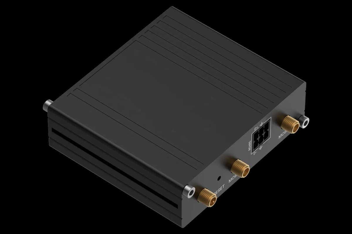
Wire the RS485 terminals A+ and B- of the AK-CC25 Pro to the RS485 port of the ModbusCloud Gateway, with a 120 ohm resistor at both ends of the bus.
Give every controller its own network address in parameter o03 and use even parity, 1 stop bit; the baud rate is detected automatically.
In ModbusCloud, add a Modbus device (RTU) with that address at 19200 baud, 8E1 and import this template.
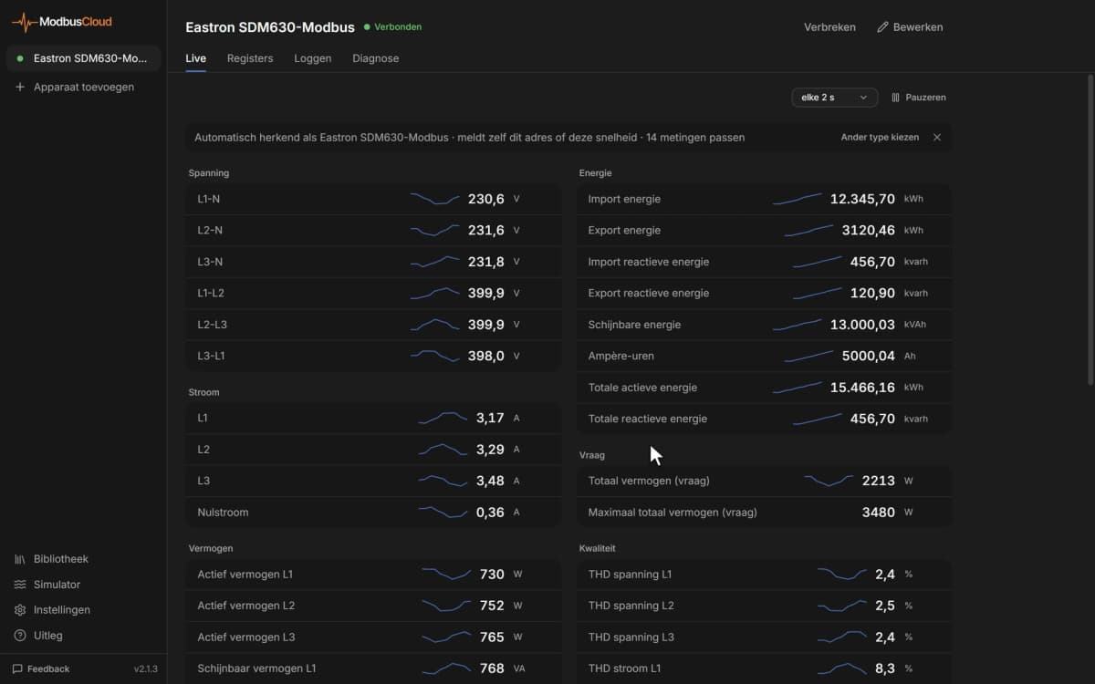
Check that the thermostat air temperature and control state match the display.
Add alarm rules on the alarm registers that matter, such as high temperature alarm A and door open alarm.
Things to watch for
The controller does not answer on the bus. What should I check?
Check that the network address in o03 is set and unique, and use even parity with 1 stop bit. The baud rate is detected automatically, so give the controller a few requests after a change. Swap A+ and B- if nothing answers, and terminate the bus with 120 ohm at both ends.
Why do some registers always read zero?
Many outputs and settings only exist in certain application modes (o61), for example rail heat, light, the second compressor or the condenser fan. In other modes these registers stay at zero or are not used.
Why are temperatures ten times too high?
Temperatures are sent as whole numbers in tenths, so 45 means 4.5. The template applies that scale. If r05 is set to Fahrenheit, the values are in °F.
How do I write setpoints or start a defrost safely?
Write the cut-out in degrees within the min and max cut-out limits. Write 1 to Start Defrost or Stop Defrost to start or end a defrost. Main switch 0 stops cooling and -1 puts the controller in manual mode, so use it only when you mean to. Agree remote changes with whoever is responsible for the cases.


Want to see how it works?