



Danfoss ERC 21x
Refrigeration controller: temperatures, relay states, setpoints, alarm and defrost parameters over Modbus RTU.
The Danfoss ERC 211, 213 and 214 are refrigeration controllers for cold rooms and display cases with one, three or four relays; this template follows the Danfoss ERC 21X Modbus parameter guide and reads temperatures, inputs and relay states and writes all setpoint, alarm, defrost, fan and compressor parameters. Connection through a TTL to RS485 converter at 19200 baud, 8 data bits, even parity, 1 stop bit, with the address set in o03.
- Protocol
- Modbus RTU
- Connection
- RS485, 19200 baud
- Registers
- 80, read and write
- Brand
- Danfoss
- Key readings
- Air temperature Sair and regulation reference · Defrost and condenser temperature · Controller status · Compressor, fan, defrost, alarm and light relay status · Digital inputs and night mode · Relay counters and firmware version
- Available commands
- Main switch r12 · Setpoint, differential and setpoint limits · High and low temperature alarm limits and delays · Defrost type, interval, stop temperature and times · Fan and compressor timers · Inputs, outputs, polarity and keyboard lock
- Compatible models
- ERC 211 · ERC 213 · ERC 214
- Last updated
Registers (80)
80 read, 62 write
| Name | Unit | Access | Address (Hidden until you enter your email) | Function (hidden) | Type (hidden) |
|---|---|---|---|---|---|
| Controller Status | Read | 2006 | FC03 | uint16 | |
| Air Temperature Sair | °C | Read | 2529 | FC03 | int16 |
| Read The Present Regulation Reference | °C | Read | 2500 | FC03 | int16 |
| Condenser Temperature Sc | °C | Read | 2646 | FC03 | int16 |
| Di1 Input | Read | 2001 | FC03 | uint16 | |
| Status on Night Operation | Read | ||||
| Compressor Relay Status | Read | ||||
| Firmware Version Readout | Read | ||||
| Defrost Sensor Temperature Sdef | °C | Read | |||
| Di2 Input | Read | ||||
| Fan Relay Status | Read | ||||
| Defrost Relay Status | Read | ||||
| Alarm Relay Status | Read | ||||
| Light Relay Status | Read | ||||
| Main Switch | Read and write | ||||
| Setpoint | °C | Read and write | |||
| Predefined Applications | Read and write | ||||
| Sensor Type Selection | Read and write | ||||
| Differential | K | Read and write | |||
| Min Setpoint Limitation | °C | Read and write | |||
| Max Setpoint Limitation | °C | Read and write | |||
| Display Offset | K | Read and write | |||
| Display Unit | Read and write | ||||
| Calibration of Sair | K | Read and write | |||
| Night Setback ECO Mode | K | Read and write | |||
| Value of Reference Displacement | °C | Read and write | |||
| Compressor Runtime Continuous Cycle | min | Read and write | |||
| Setpoint at Continuous Cycle Exit | °C | Read and write | |||
| Alarm Delay | min | Read and write | |||
| Alarm Delay Pulldown Start up Defrost | min | Read and write | |||
| High Temperature Alarm Limit | °C | Read and write | |||
| Low Temperature Alarm Limit | °C | Read and write | |||
| DI1 Delay | min | Read and write | |||
| Condenser High Alarm Limit | °C | Read and write | |||
| Condenser High Block Limit | °C | Read and write | |||
| Voltage Protection | Read and write | ||||
| Minimum Cut-in Voltage | V | Read and write | |||
| Minimum Cut-out Voltage | V | Read and write | |||
| Maximum Voltage | V | Read and write | |||
| Defrost Type | Read and write | ||||
| Defrost Stop Temperature | °C | Read and write | |||
| Defrost Interval | h | Read and write | |||
| Max Defrost Time | min | Read and write | |||
| Defrost Delay at Power up | min | Read and write | |||
| Drip Delay | min | Read and write | |||
| Defrost Stop Sensor | Read and write | ||||
| Compressor Accumulated Runtime to Start Defrost | h | Read and write | |||
| Defrost Delay After Continuous Cycle | min | Read and write | |||
| Compressor Min ON Time | min | Read and write | |||
| Compressor Min OFF Time | min | Read and write | |||
| Compressor OFF Delay at Open Door | Read and write | ||||
| Zero Crossing Selection | Read and write | ||||
| Delay of Outputs at Startup | s | Read and write | |||
| DI1 Configuration | Read and write | ||||
| Serial Address | Read and write | ||||
| Password | Read and write | ||||
| Cooling Heating | Read and write | ||||
| Display Resolution | Read and write | ||||
| Relay 1 Counter | Read | ||||
| Save Settings As Factory | Read and write | ||||
| Display at Defrost | Read and write | ||||
| DI1 Input Polarity | Read and write | ||||
| Key Board Lock | Read and write | ||||
| DO2 Config | Read and write | ||||
| DI2 Delay | min | Read and write | |||
| Fan Delay After Defrost | min | Read and write | |||
| Fan Start Temperature After Defrost | °C | Read and write | |||
| Fan During Defrost | Read and write | ||||
| Defrost on Demand | K | Read and write | |||
| Fan at Comp OFF | Read and write | ||||
| Fan Stop Evap Temperature | °C | Read and write | |||
| Fan ON Cycle | min | Read and write | |||
| Fan OFF Cycle | min | Read and write | |||
| Relay 2 Counter | Read | ||||
| Relay 3 Counter | Read | ||||
| DI2 Config | Read and write | ||||
| DI2 Input Polarity | Read and write | ||||
| Invert Alarm Relay | Read and write | ||||
| Relay 4 Counter | Read | ||||
| DO4 Config | Read and write |
Loading registers…
Send your device list
If a device is not in the library yet, we build the template for free as soon as we have the register data.
Use cases
- Alert when Air Temperature Sair rises above High Temperature Alarm Limit for longer than Alarm Delay in a cold room.
- Log Compressor Relay Status and Defrost Relay Status to check defrost cycles and compressor running time.
- Watch Condenser Temperature Sc to plan condenser cleaning before Condenser High Block Limit stops the compressor.
- Change Setpoint remotely for night or weekend operation of a display case.
- Read Relay 1 Counter to plan relay replacement on a heavily switching controller.
Installation
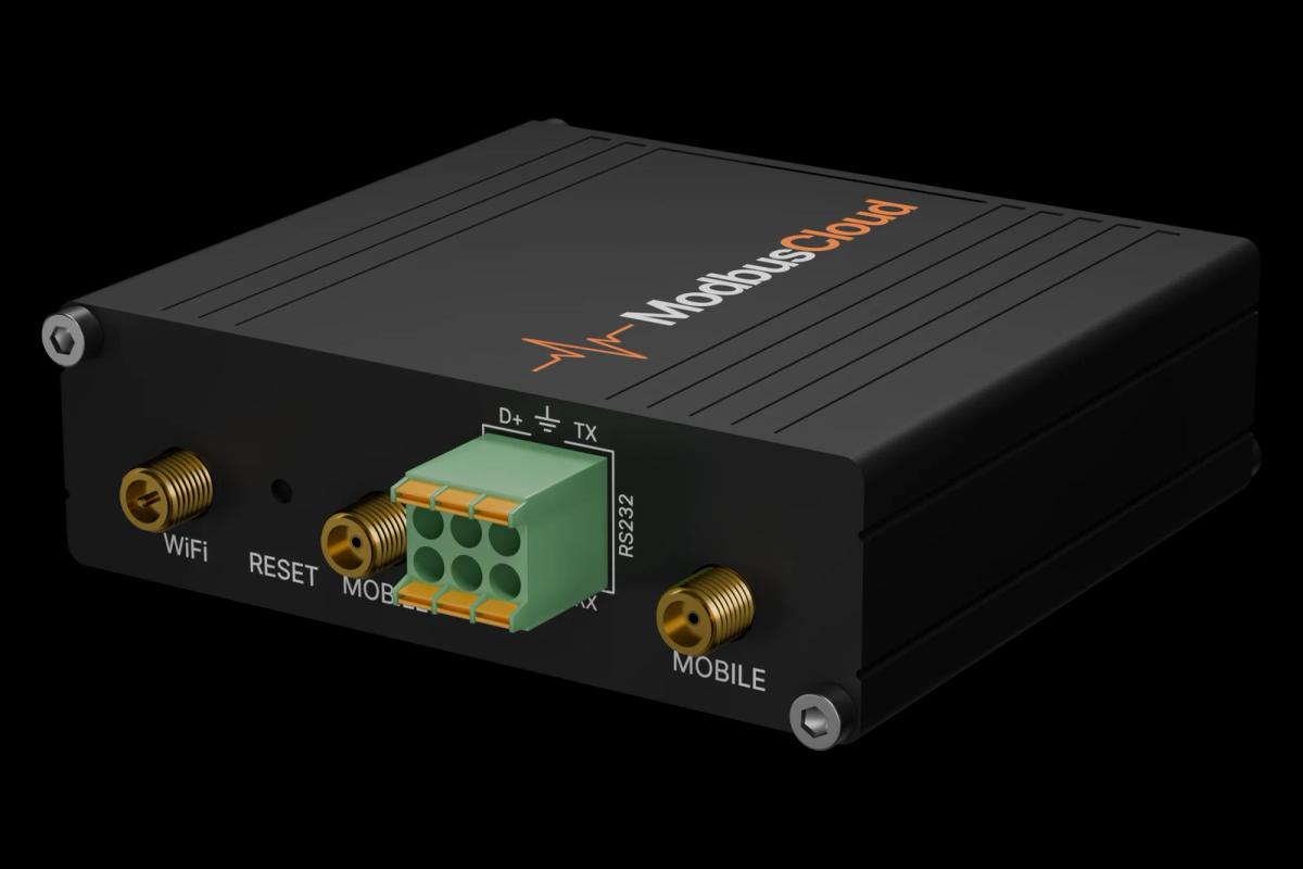
Connect the ERC programming port through a TTL to RS485 converter to the RS485 port of your ModbusCloud Gateway. Terminate both ends of the bus.
On the controller set the Modbus address in parameter o03 to a value from 1 to 247; the default 0 does not answer.
In ModbusCloud, add a Modbus device (RTU) with that address, 19200 baud, 8 data bits, even parity and 1 stop bit, then import this template.
Check the link: Air Temperature Sair should match the controller display and Setpoint the value of r00.
Things to watch for
The ERC does not answer on the bus. What should I check?
The ERC has no RS485 terminals; communication needs a TTL to RS485 converter on the programming port. Check that o03 is set to an address from 1 to 247 (default 0), that the master uses 19200 baud, 8E1, and swap A and B on the converter side if needed.
Why do temperatures read 250 instead of 2.5 °C?
Temperatures are signed 16-bit integers with scale 0.01. The template applies the scale; if you read the registers yourself, divide by 100.
Some registers return an exception.
Not every register exists on every model. The fan, defrost and alarm relays, DI2 and the fan parameters are only on the ERC 213 and 214, the light relay and DO4 config only on the ERC 214, Cooling Heating only on the ERC 211. The comment of each register names the models.
Writing the sensor type or application has no effect.
Parameters o06, o61, o07, o36 and o71 can only be changed when regulation is stopped. Write 0 to Main Switch first, change the parameter and switch regulation on again.


Want to see how it works?