

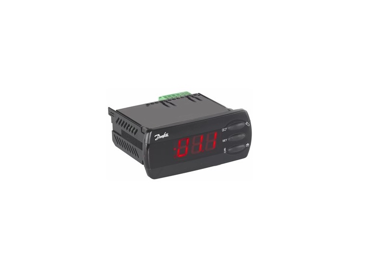
Danfoss EKC 202D1
Danfoss
Refrigeration controller: air and defrost temperatures, alarms, setpoint and defrost control.
Overview
Key readings
- Air temperature
- Display temperature
- Evaporator temperature
- Controller state
- Defrost status
- High temperature alarm
Available commands
- Temperature setpoint
- Main switch
- Defrost start
- Night setback
- Alarm limits
Use cases
- Show the air temperature of every display case and cold room on one dashboard.
- Get an email when the high temperature alarm becomes active or the air temperature passes a limit you set.
- Keep 365 days of temperature history per case as a record for food safety checks.
- Raise the setpoint at night with an automation on a schedule through night setback.
- Start a defrost or acknowledge an alarm remotely instead of walking to the case.
Installation
- 1Plug the EKA 178A module into the controller and connect its RS485 terminals to the RS485 A and B terminals of the ModbusCloud Gateway; terminate the bus at both ends.
- 2Set the application in o61 first, then the network address in o03 (1 to 240).
- 3In ModbusCloud, add a Modbus device (RTU) with the same address, 9600 baud, 8 data bits, even parity and 1 stop bit, and import this template.
- 4Check that the air temperature matches the display of the controller.
Things to watch for
- The controller does not answer. What should I check?
- Check that the EKA 178A module is fitted and that o03 holds an address from 1 to 240; the factory value 0 means no address. Try 9600 baud with even parity. Swap A and B if nothing comes back and terminate the bus at both ends.
- Why are temperatures ten times too high or in Fahrenheit?
- Temperatures come in tenths and the template divides them by 10. When r05 is set to °F, all temperatures and limits are in Fahrenheit. Some values only exist in one application: light, alarm relay and rail heat follow the setting in o61.
- Can several controllers share one RS485 line?
- Yes. Give each controller its own address in o03 and use the same serial settings on all of them. Wire the bus as one line from controller to controller and terminate both ends.
- What should I keep in mind when I write a setting?
- A write takes effect immediately. The setpoint must stay within r02 and r03. Relays can only be switched by hand when the main switch r12 is set to -1 (service); set it back to 1 to resume control. Change one setting at a time and check the display.
Registers (117)
117 read / 81 write
| Name | Address | Function | Type | Unit | Access |
|---|---|---|---|---|---|
| Thermostat Air Temperature | ••• | ••• | ••• | °C | R |
| S3 Air Temperature | ••• | ••• | ••• | °C | R |
| S4 Air Temperature | ••• | ••• | ••• | °C | R |
| S5 Evaporator Temperature | ••• | ••• | ••• | °C | R |
| S5B Temperature | ••• | ••• | ••• | °C | R |
| Display Air Temperature | ••• | ••• | ••• | °C | R |
| Alarm Air Temperature | ••• | ••• | ••• | °C | R |
| Temperature Reference | ••• | ••• | ••• | °C | R |
| Controller State | ••• | ••• | ••• | R | |
| DI1 Status | ••• | ••• | ••• | R | |
| DI2 Status | ••• | ••• | ••• | R | |
| Night Condition | ••• | ••• | ••• | R | |
| Defrost State | ••• | ••• | ••• | R | |
| Night Cover Detected | ••• | ••• | ••• | R | |
| Controller Error | ••• | ••• | ••• | R | |
| Controller Error Alarm | ••• | ••• | ••• | R | |
| Clock Error Alarm | ••• | ••• | ••• | R | |
| S3 Sensor Error Alarm | ••• | ••• | ••• | R | |
| S4 Sensor Error Alarm | ••• | ••• | ••• | R | |
| S5 Sensor Error Alarm | ••• | ••• | ••• | R | |
| S5B Sensor Error Alarm | ••• | ••• | ••• | R | |
| High Temperature Alarm | ••• | ••• | ••• | R | |
| Low Temperature Alarm | ••• | ••• | ••• | R | |
| S3 High Temperature Alarm | ••• | ••• | ••• | R | |
| S3 Low Temperature Alarm | ••• | ••• | ••• | R | |
| Door Alarm | ••• | ••• | ••• | R | |
| DI1 Alarm | ••• | ••• | ••• | R | |
| DI2 Alarm | ••• | ••• | ••• | R | |
| Max Defrost Time Alarm | ••• | ••• | ••• | R | |
| Max Hold Time Alarm | ••• | ••• | ••• | R | |
| Case Cleaning Alarm | ••• | ••• | ••• | R | |
| S3 S4 Swapped Alarm | ••• | ••• | ••• | R | |
| Standby Mode Alarm | ••• | ••• | ••• | R | |
| Main Switch | ••• | ••• | ••• | R/W | |
| Temperature Setpoint | ••• | ••• | ••• | °C | R/W |
| Thermostat Differential | ••• | ••• | ••• | K | R/W |
| Max Setpoint Limit | ••• | ••• | ••• | °C | R/W |
| Min Setpoint Limit | ••• | ••• | ••• | °C | R/W |
| Night Setback | ••• | ••• | ••• | R/W | |
| Forced Cooling | ••• | ••• | ••• | R/W | |
| Defrost Start | ••• | ••• | ••• | R/W | |
| Reset Alarm | ••• | ••• | ••• | R/W | |
| Display Adjustment | ••• | ••• | ••• | K | R/W |
| Temperature Unit | ••• | ••• | ••• | R/W | |
| S4 Sensor Adjustment | ••• | ••• | ••• | K | R/W |
| S3 Sensor Adjustment | ••• | ••• | ••• | K | R/W |
| Night Offset | ••• | ••• | ••• | K | R/W |
| Thermostat S4 Weighting | ••• | ••• | ••• | % | R/W |
| Display S4 Weighting | ••• | ••• | ••• | % | R/W |
| Thermostat Offset Enable | ••• | ••• | ••• | R/W | |
| Thermostat Offset | ••• | ••• | ••• | K | R/W |
| Thermostat S4 Weighting Night | ••• | ••• | ••• | % | R/W |
| Night Cover Difference | ••• | ••• | ••• | K | R/W |
| Compressor Min On Time | ••• | ••• | ••• | min | R/W |
| Compressor Min Off Time | ••• | ••• | ••• | min | R/W |
| Compressor Relay NC | ••• | ••• | ••• | R/W | |
| Defrost Method | ••• | ••• | ••• | R/W | |
| Defrost Stop Temperature | ••• | ••• | ••• | °C | R/W |
| Defrost Interval | ••• | ••• | ••• | h | R/W |
| Max Defrost Time | ••• | ••• | ••• | min | R/W |
| Defrost Start Delay | ••• | ••• | ••• | min | R/W |
| Drip Off Time | ••• | ••• | ••• | min | R/W |
| Fan Start Delay | ••• | ••• | ••• | min | R/W |
| Fan Start Temperature | ••• | ••• | ••• | °C | R/W |
| Fan During Defrost | ••• | ••• | ••• | R/W | |
| Defrost Stop Sensor | ••• | ••• | ••• | R/W | |
| Pump Down Delay | ••• | ••• | ••• | min | R/W |
| Max Cooling Time Between Defrosts | ••• | ••• | ••• | h | R/W |
| Demand Defrost S5 Difference | ••• | ••• | ••• | K | R/W |
| Hold After Defrost | ••• | ••• | ••• | R/W | |
| Min Defrost Time | ••• | ••• | ••• | min | R/W |
| Max Hold Time | ••• | ••• | ••• | min | R/W |
| Defrost 1 Start Hour | ••• | ••• | ••• | h | R/W |
| Defrost 1 Start Minute | ••• | ••• | ••• | min | R/W |
| Defrost 2 Start Hour | ••• | ••• | ••• | h | R/W |
| Defrost 2 Start Minute | ••• | ••• | ••• | min | R/W |
| Defrost 3 Start Hour | ••• | ••• | ••• | h | R/W |
| Defrost 3 Start Minute | ••• | ••• | ••• | min | R/W |
| Defrost 4 Start Hour | ••• | ••• | ••• | h | R/W |
| Defrost 4 Start Minute | ••• | ••• | ••• | min | R/W |
| Defrost 5 Start Hour | ••• | ••• | ••• | h | R/W |
| Defrost 5 Start Minute | ••• | ••• | ••• | min | R/W |
| Defrost 6 Start Hour | ••• | ••• | ••• | h | R/W |
| Defrost 6 Start Minute | ••• | ••• | ••• | min | R/W |
| Fan Stop With Compressor | ••• | ••• | ••• | R/W | |
| Fan Stop Delay | ••• | ••• | ••• | min | R/W |
| Fan Stop Temperature | ••• | ••• | ••• | °C | R/W |
| Temperature Alarm Delay | ••• | ••• | ••• | min | R/W |
| Door Alarm Delay | ••• | ••• | ••• | min | R/W |
| Alarm Delay After Defrost | ••• | ••• | ••• | min | R/W |
| High Alarm Limit | ••• | ••• | ••• | °C | R/W |
| Low Alarm Limit | ••• | ••• | ••• | °C | R/W |
| DI1 Alarm Delay | ••• | ••• | ••• | min | R/W |
| DI2 Alarm Delay | ••• | ••• | ••• | min | R/W |
| Alarm Sensor Configuration | ••• | ••• | ••• | R/W | |
| Alarm S4 Weighting | ••• | ••• | ••• | % | R/W |
| S3 High Alarm Limit | ••• | ••• | ••• | °C | R/W |
| S3 Low Alarm Limit | ••• | ••• | ••• | °C | R/W |
| Output Delay After Start | ••• | ••• | ••• | s | R/W |
| DI1 Function | ••• | ••• | ••• | R/W | |
| DI2 Function | ••• | ••• | ••• | R/W | |
| Sensor Type | ••• | ••• | ••• | R/W | |
| Case Cleaning | ••• | ••• | ••• | R/W | |
| Light Configuration | ••• | ••• | ••• | R/W | |
| Light Remote | ••• | ••• | ••• | R/W | |
| Rail Heat On Day | ••• | ••• | ••• | % | R/W |
| Rail Heat On Night | ••• | ••• | ••• | % | R/W |
| Rail Heat Cycle Time | ••• | ••• | ••• | min | R/W |
| Compressor Relay | ••• | ••• | ••• | R/W | |
| Defrost Relay | ••• | ••• | ••• | R/W | |
| Fan Relay | ••• | ••• | ••• | R/W | |
| Alarm Relay | ••• | ••• | ••• | R/W | |
| Light Relay | ••• | ••• | ••• | R/W | |
| Rail Heat Relay | ••• | ••• | ••• | R/W | |
| Application Mode | ••• | ••• | ••• | R | |
| Module Software Version | ••• | ••• | ••• | R | |
| Transceiver Type | ••• | ••• | ••• | R |
Loading registers…
Read the Danfoss EKC 202D1 remotely
We load the templates onto the gateway and set up your portal, you connect it at your customer's site. Tell us briefly what you need and we'll send a proposal.
From €295 + €149/year.
Prefer to configure it yourself? Order the gateway in the shop·Or see the live demo first
More Danfoss templates
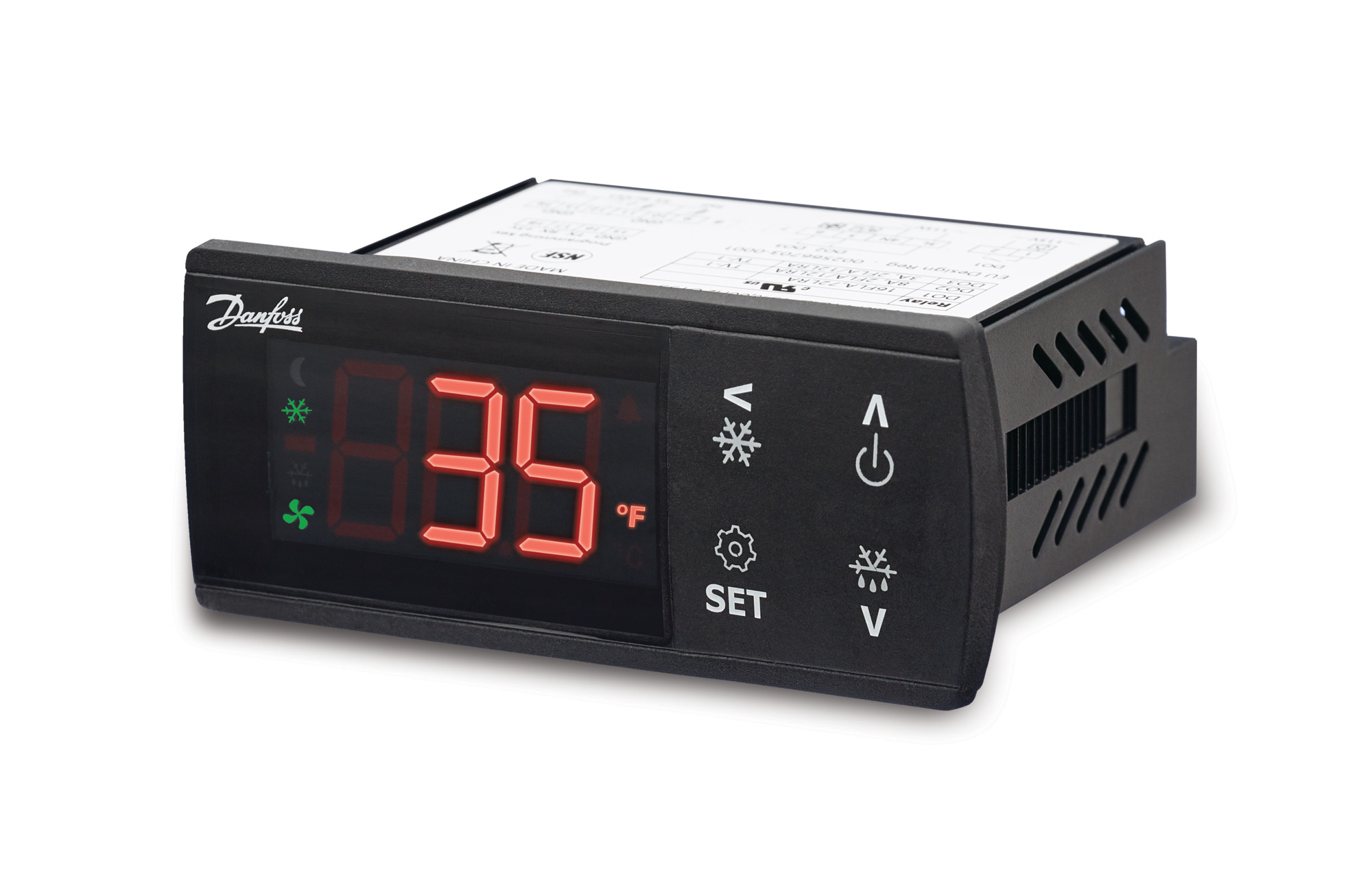
Danfoss ERC 21x
Danfoss
Refrigeration controller: temperatures, relay states, setpoints, alarm and defrost parameters over Modbus RTU.
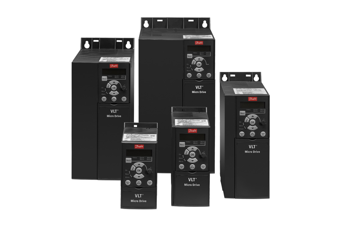
Danfoss VLT Micro Drive FC 51
Danfoss
Compact frequency converter: frequency, current, power, temperatures, alarm and warning words and hour counters over Modbus RTU.
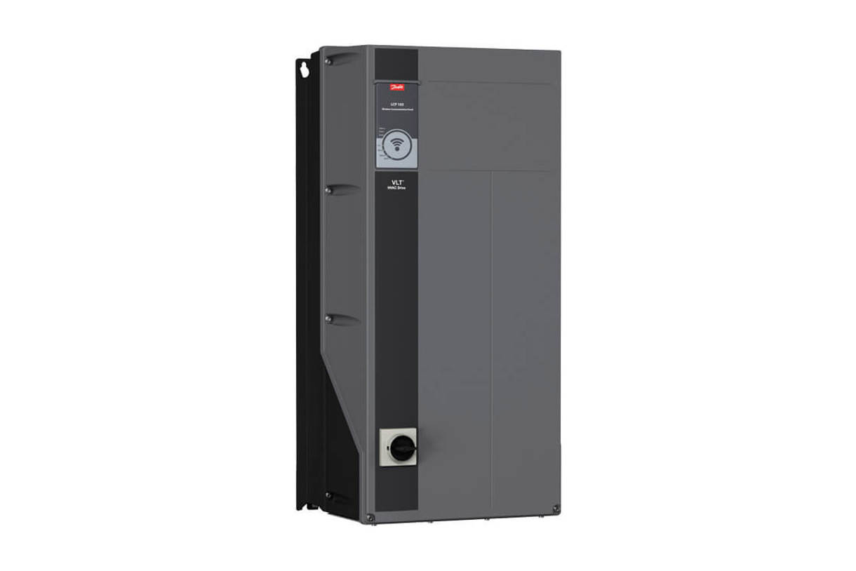
Danfoss VLT HVAC Drive FC 102
Danfoss
Frequency converter for HVAC fans and pumps: motor readings, alarms, start and stop, speed reference and settings.
More RTU templates

Alnor HRU
Alnor Systemy Wentylacji Sp. z o. o.
Controls and monitors Alnor heat recovery ventilation units via Modbus RTU.

Alnor HRU-P
Alnor Systemy Wentylacji Sp. z o. o.
Controls Alnor HRU-P heat recovery ventilation units via Modbus RTU.

connecdoor.controller
connecdoor
Controls and monitors smart door access points via RS485
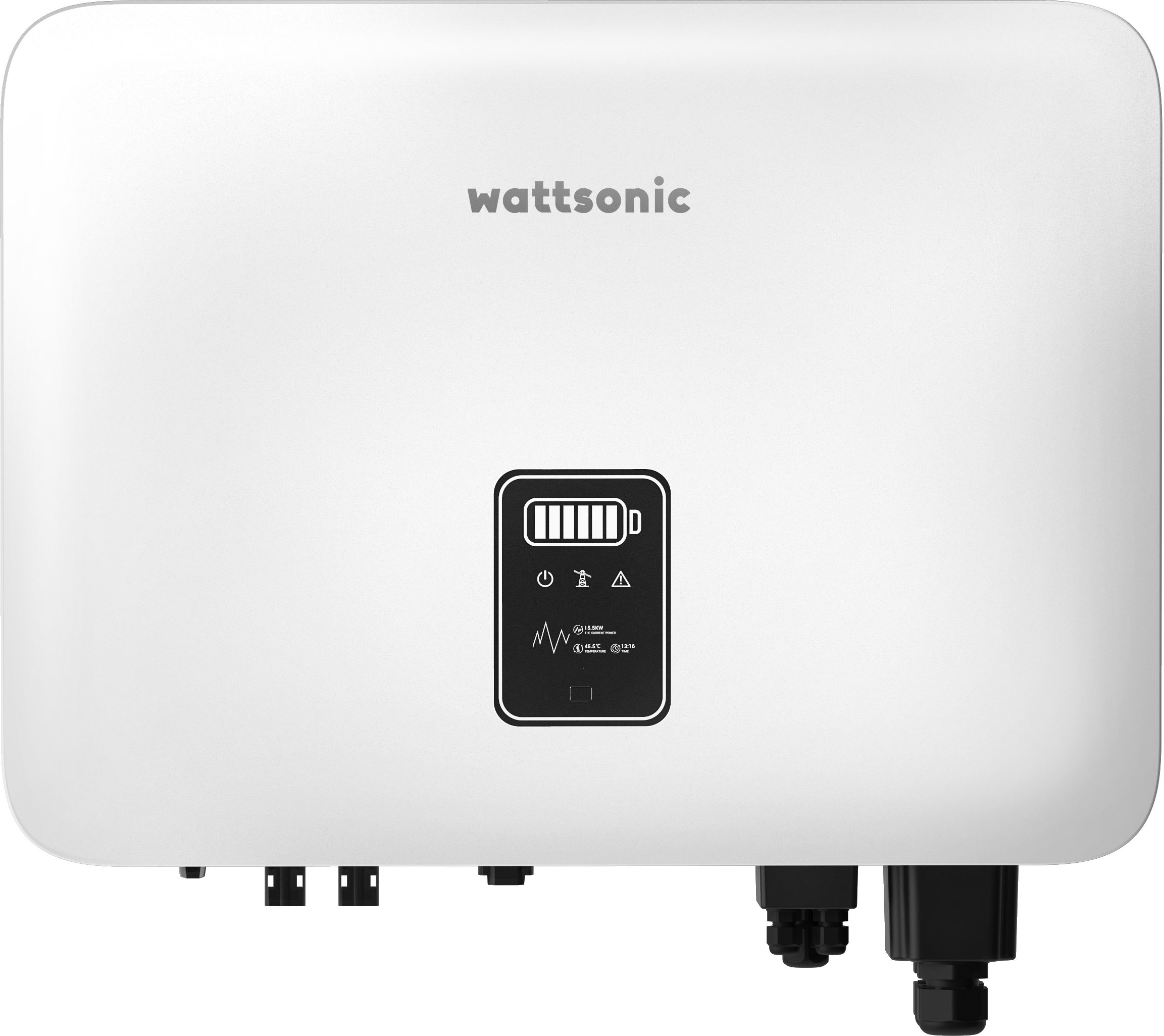
Wattsonic - Schmachtl Sun Energy Box
Wattsonic
Monitors Schmachtl Wattsonic hybrid inverter via Modbus RTU

Heidelberg Wallbox Energy Control
AMPERFIED GmbH
Controls and monitors Heidelberg Wallbox Energy Control EV charger via Modbus RTU.
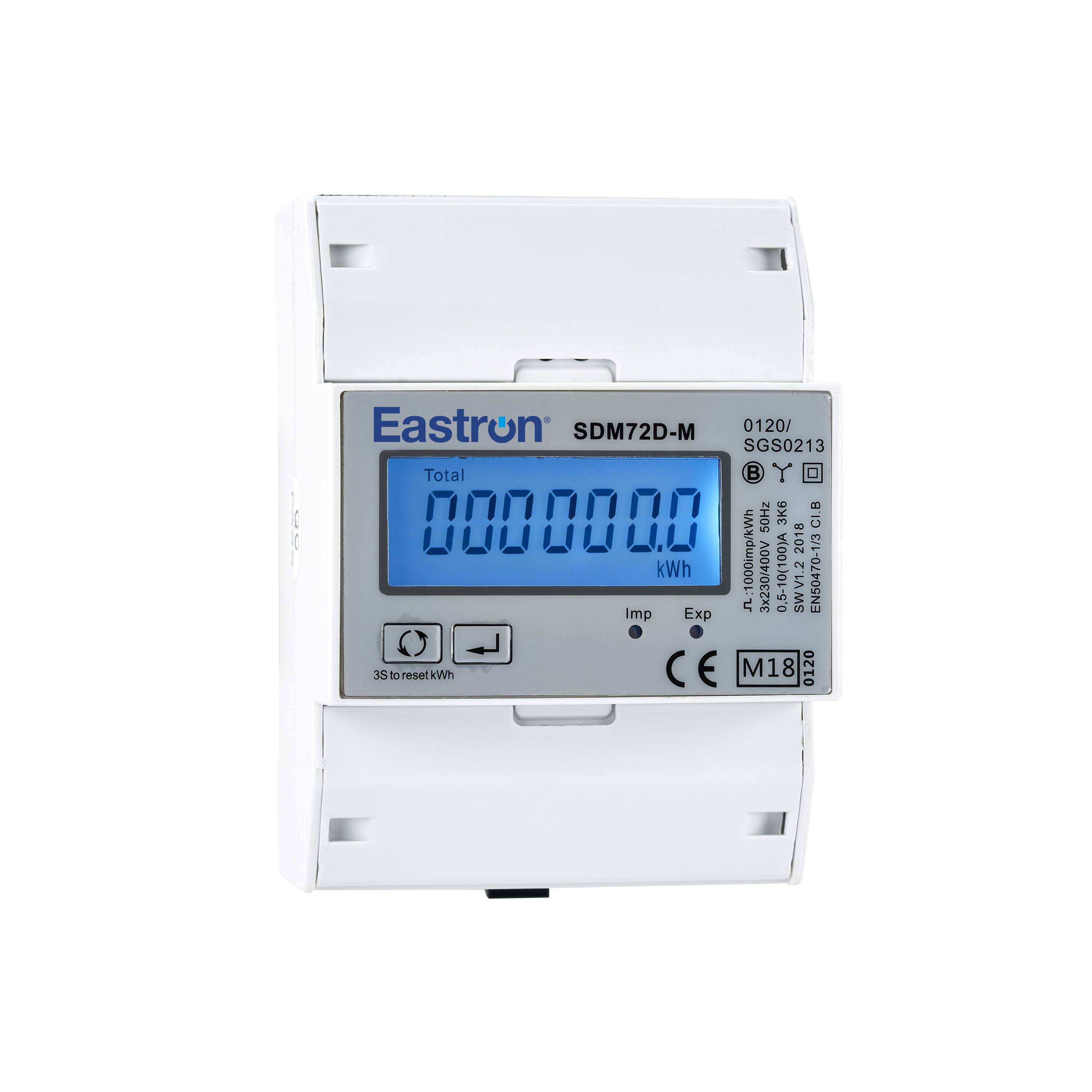
Eastron SDM72D-M
Eastron
Reads energy metering values from an Eastron SDM72D-M three-phase meter.