

Danfoss AK-CC55 Multi Coil
Case and room controller for up to three evaporators with electronic expansion valves.
The Danfoss AK-CC55 Multi Coil is a case and room controller that runs up to three evaporator sections with electronic expansion valves in refrigerated cabinets and cold rooms. This Modbus RTU template reads air, food and defrost temperatures, superheat, valve opening, control state and alarms per section, and lets you set cut-out, differential, defrost and alarm limits from ModbusCloud.
- Protocol
- Modbus RTU
- Connection
- RS485, 19200 baud
- Registers
- 81, read and write
- Brand
- Danfoss
- Key readings
- Thermostat air temperature · Food temperature · Evaporating temperature · Superheat · Expansion valve opening · Control state · Alarms
- Available commands
- Main switch · Cut-out temperature · Differential · Defrost start · Alarm limits
- Compatible models
- AK-CC55 Multi Coil · 084B4084
- Last updated
Registers (81)
81 read, 13 write
| Name | Unit | Access | Address (Hidden until you enter your email) | Function (hidden) | Type (hidden) |
|---|---|---|---|---|---|
| Thermostat Air Temperature A | °C | Read | |||
| Thermostat Air Temperature B | °C | Read | |||
| Thermostat Air Temperature C | °C | Read | |||
| Food Temperature | °C | Read | |||
| Evaporating Temperature | °C | Read | |||
| S2 Temperature A | °C | Read | |||
| S2 Temperature B | °C | Read | |||
| S2 Temperature C | °C | Read | |||
| S4 Air Temperature A | °C | Read | |||
| S4 Air Temperature B | °C | Read | |||
| S4 Air Temperature C | °C | Read | |||
| S5 Temperature A | °C | Read | |||
| S5 Temperature B | °C | Read | |||
| Alarm Air Temperature A | °C | Read | |||
| Alarm Air Temperature B | °C | Read | |||
| Alarm Air Temperature C | °C | Read | |||
| Superheat A | °C | Read | |||
| Superheat Reference A | °C | Read | |||
| Superheat B | °C | Read | |||
| Superheat Reference B | °C | Read | |||
| Superheat C | °C | Read | |||
| Superheat Reference C | °C | Read | |||
| Expansion Valve Opening A | % | Read | |||
| Expansion Valve Opening B | % | Read | |||
| Expansion Valve Opening C | % | Read | |||
| Defrost Sensor Temperature A | °C | Read | |||
| Defrost Sensor Temperature B | °C | Read | |||
| Defrost Sensor Temperature C | °C | Read | |||
| Thermostat Cut In Temperature | °C | Read | |||
| Thermostat Cut Out Temperature | °C | Read | |||
| Sum Alarm | Read | ||||
| Control State A | Read | ||||
| Control State B | Read | ||||
| Control State C | Read | ||||
| Thermostat Band | Read | ||||
| Night Condition | Read | ||||
| Controller Error | Read | ||||
| RTC Error | Read | ||||
| Pe Error | Read | ||||
| S2 Error A | Read | ||||
| S4 Error A | Read | ||||
| S5 Error A | Read | ||||
| S5 Error B | Read | ||||
| RH Input Error | Read | ||||
| S4 Error B | Read | ||||
| S4 Error C | Read | ||||
| S2 Error B | Read | ||||
| S2 Error C | Read | ||||
| High Temperature Alarm A | Read | ||||
| Low Temperature Alarm A | Read | ||||
| Door Alarm | Read | ||||
| Max Hold Time Alarm | Read | ||||
| No Refrigerant Selected | Read | ||||
| DI1 Alarm | Read | ||||
| DI2 Alarm | Read | ||||
| Standby Mode | Read | ||||
| Case Cleaning | Read | ||||
| High Temperature Alarm B | Read | ||||
| Low Temperature Alarm B | Read | ||||
| CO2 Alarm | Read | ||||
| Refrigerant Leak Alarm | Read | ||||
| High Humidity Alarm | Read | ||||
| Low Humidity Alarm | Read | ||||
| High Temperature Alarm C | Read | ||||
| Low Temperature Alarm C | Read | ||||
| Max Defrost Time Alarm A | Read | ||||
| Max Defrost Time Alarm B | Read | ||||
| Max Defrost Time Alarm C | Read | ||||
| Main Switch | Read and write | ||||
| Cutout 1 | °C | Read and write | |||
| Differential 1 | °C | Read and write | |||
| Cutout 2 | °C | Read and write | |||
| Differential 2 | °C | Read and write | |||
| Defrost Start | Read and write | ||||
| Defrost Stop Temperature 1 | °C | Read and write | |||
| Defrost Stop Temperature 2 | °C | Read and write | |||
| Max Defrost Time 1 | min | Read and write | |||
| Max Defrost Time 2 | min | Read and write | |||
| Alarm Delay | min | Read and write | |||
| High Air Temperature Limit 1 | °C | Read and write | |||
| Low Air Temperature Limit 1 | °C | Read and write |
Loading registers…
Send your device list
If a device is not in the library yet, we build the template for free as soon as we have the register data.
Use cases
- Show air and food temperature of every cabinet section on one dashboard for a store manager.
- Send an email when the high or low temperature alarm of a section becomes active.
- Keep a year of temperature history per section as evidence for food safety audits.
- Compare superheat with its reference to spot an expansion valve that hunts or a refrigerant shortage.
- Change the cut-out or defrost stop temperature remotely without a visit to the store.
- Start a manual defrost from the portal when a section ices up.
Installation
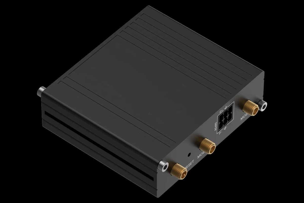
Connect the ModbusCloud Gateway RS485 A and B to terminals 84 (A+) and 83 (B-), the screen to 85, and terminate both ends of the bus.
Set the network address o03 on the controller to a free address between 1 and 240; the factory value 0 does not answer.
Leave the controller on automatic baud rate detection and set the Gateway to 19200 baud, 8 data bits, even parity, 1 stop bit.
In ModbusCloud, add a Modbus device on the Gateway with that address and import the Danfoss AK-CC55 Multi Coil template.
Check that air temperature and control state of section A come in, then remove the section B and C registers you do not use.
Things to watch for
Why does the controller not answer at all?
Check that o03 is not 0, because the controller does not answer on address 0. Then check A+ and B-, swap them once if needed, and make sure the bus is terminated at both ends. Every controller on the line needs its own address.
Why do section B and C registers show nothing or an error?
Those values only exist in application modes with two or three evaporators. In a mode with one evaporator the controller does not provide them; remove those registers from the device in ModbusCloud.
Why does a temperature look ten times too high?
The controller sends temperatures in tenths of a degree. The template already applies a factor of 0.1. If you entered registers by hand, set the scale to 0.1.
Can I connect several AK-CC55 controllers to one Gateway?
Yes. Give each controller a different network address in o03 and add each one as a separate Modbus device with this template. Up to 32 devices fit on one RS485 line.
What should I watch out for when writing settings?
Read the current value first and stay inside the controller limits; r00 is held between r02 and r03, and some settings are only accepted when the main switch r12 is at stop. Writing 0 to the main switch stops refrigeration of the whole case.


Want to see how it works?