


Danfoss VLT AutomationDrive FC 360
General purpose frequency converter for conveyors, pumps, fans and machines with built-in Modbus RTU.
The Danfoss VLT AutomationDrive FC 360 is a frequency converter that controls the speed of motors on conveyors, pumps, fans and machines in industry. This Modbus RTU template reads frequency, current, power, torque, temperatures and status and alarm words and lets you start, stop and set the speed and change drive parameters from ModbusCloud.
- Protocol
- Modbus RTU
- Connection
- RS485, 9600 baud
- Registers
- 832, read and write
- Brand
- Danfoss
- Key readings
- Output frequency · Motor current · Power · Torque · DC link voltage · Status word · Alarm word
- Available commands
- Start and stop · Speed reference · Ramp times · Speed limits · Motor data
- Compatible models
- FC 360 · VLT AutomationDrive FC 360
- Last updated
Registers (832)
800 read, 682 write
| Name | Unit | Access | Address (Hidden until you enter your email) | Function (hidden) | Type (hidden) |
|---|---|---|---|---|---|
| Control Word (16-00) | Read | ||||
| Reference Unit (16-01) | Read | ||||
| Reference % (16-02) | % | Read | |||
| Status Word (16-03) | Read | ||||
| Main Actual Value % (16-05) | % | Read | |||
| Custom Readout (16-09) | Read | ||||
| Power kW (16-10) | kW | Read | |||
| Power hp (16-11) | Read | ||||
| Motor Voltage (16-12) | V | Read | |||
| Frequency (16-13) | Hz | Read | |||
| Motor current (16-14) | A | Read | |||
| Frequency % (16-15) | % | Read | |||
| Torque Nm (16-16) | Nm | Read | |||
| Speed RPM (16-17) | rpm | Read | |||
| Motor Thermal (16-18) | % | Read | |||
| Motor Angle (16-20) | Read | ||||
| Torque % (16-22) | % | Read | |||
| Calibrated Stator Resistance (16-24) | Ω | Read | |||
| DC Link Voltage (16-30) | V | Read | |||
| Brake Energy/2 min (16-33) | kW | Read | |||
| Heat sink Temp. (16-34) | °C | Read | |||
| Inverter Thermal (16-35) | % | Read | |||
| Inv. Nom. Current (16-36) | A | Read | |||
| Inv. Max. Current (16-37) | A | Read | |||
| SL Controller State (16-38) | Read | ||||
| Control Card Temp. (16-39) | °C | Read | |||
| Logging Buffer Full (16-40) | Read | ||||
| Service Log Counter (16-42) | Read | ||||
| Speed Error RPM (16-44) | Read | ||||
| Speed Ref. After Ramp RPM (16-48) | rpm | Read | |||
| External Reference (16-50) | % | Read | |||
| FeedbackUnit (16-52) | Read | ||||
| Digi Pot Reference (16-53) | Read | ||||
| Feedback RPM (16-57) | rpm | Read | |||
| Digital Input (16-60) | Read | ||||
| Terminal 53 Setting (16-61) | Read | ||||
| Analog input 53 (16-62) | Read | ||||
| Terminal 54 Setting (16-63) | Read | ||||
| Analog input 54 (16-64) | Read | ||||
| Analog output 42 mA (16-65) | mA | Read | |||
| Digital Output (16-66) | Read | ||||
| Pulse input 29 Hz (16-67) | Read | ||||
| Pulse input 33 Hz (16-68) | Read | ||||
| Pulse output 27 Hz (16-69) | Read | ||||
| Pulse output 29 Hz (16-70) | Read | ||||
| Relay output (16-71) | Read | ||||
| Counter A (16-72) | Read | ||||
| Counter B (16-73) | Read | ||||
| Analog output 45 mA (16-79) | mA | Read | |||
| Fieldbus CTW 1 (16-80) | Read | ||||
| Fieldbus REF 1 (16-82) | Read | ||||
| Comm. Option STW (16-84) | Read | ||||
| FC Port CTW 1 (16-85) | Read | ||||
| FC Port REF 1 (16-86) | Read | ||||
| Fieldbus Torque FF. (16-88) | Read | ||||
| Alarm Word (16-90) | Read | ||||
| Alarm Word 2 (16-91) | Read | ||||
| Warning Word (16-92) | Read | ||||
| Warning Word 2 (16-93) | Read | ||||
| Ext. Status Word (16-94) | Read | ||||
| Ext. Status Word 2 (16-95) | Read | ||||
| Alarm Word 3 (16-97) | Read | ||||
| Status Word Coil 33 Control Ready | Read | ||||
| Status Word Coil 34 Drive Ready | Read | ||||
| Status Word Coil 35 Coast Stop Or Safety Closed | Read | ||||
| Status Word Coil 36 Alarm | Read | ||||
| Status Word Coil 37 Unused 37 | Read | ||||
| Status Word Coil 38 Unused 38 | Read | ||||
| Status Word Coil 39 Unused 39 | Read | ||||
| Status Word Coil 40 Warning | Read | ||||
| Status Word Coil 41 At Reference | Read | ||||
| Status Word Coil 42 Hand Or Auto Mode | Read | ||||
| Status Word Coil 43 In Frequency Range | Read | ||||
| Status Word Coil 44 Running | Read | ||||
| Status Word Coil 45 Unused 45 | Read | ||||
| Status Word Coil 46 Voltage Warning | Read | ||||
| Status Word Coil 47 Current Limit | Read | ||||
| Status Word Coil 48 Thermal Warning | Read | ||||
| Main Actual Value Coil 49 | Read | ||||
| Main Actual Value Coil 50 | Read | ||||
| Main Actual Value Coil 51 | Read | ||||
| Main Actual Value Coil 52 | Read | ||||
| Main Actual Value Coil 53 | Read | ||||
| Main Actual Value Coil 54 | Read | ||||
| Main Actual Value Coil 55 | Read | ||||
| Main Actual Value Coil 56 | Read | ||||
| Main Actual Value Coil 57 | Read | ||||
| Main Actual Value Coil 58 | Read | ||||
| Main Actual Value Coil 59 | Read | ||||
| Main Actual Value Coil 60 | Read | ||||
| Main Actual Value Coil 61 | Read | ||||
| Main Actual Value Coil 62 | Read | ||||
| Main Actual Value Coil 63 | Read | ||||
| Main Actual Value Coil 64 | Read | ||||
| Operating hours (15-00) | h | Read | |||
| Running Hours (15-01) | h | Read | |||
| kWh Counter (15-02) | kWh | Read | |||
| Power Up's (15-03) | Read | ||||
| Over Temp's (15-04) | Read | ||||
| Overvolt's (15-05) | Read | ||||
| Reset kWh Counter (15-06) | Read | ||||
| Reset Running Hours Counter (15-07) | Read | ||||
| Info Message: "Service Log Full" (15-15) | Read | ||||
| Service Log Trigger Alarm (15-17) | Read | ||||
| Service Log Trigger SLC (15-18) | Read | ||||
| Alarm Log: Error Code (15-30) | Read | ||||
| InternalFaultReason (15-31) | Read | ||||
| Alarm Log: Time (15-32) | s | Read | |||
| FC Type (15-40) | Read | ||||
| Power Section (15-41) | Read | ||||
| Voltage (15-42) | Read | ||||
| Software Version (15-43) | Read | ||||
| Ordered Type Code (15-44) | Read | ||||
| Actual Typecode String (15-45) | Read | ||||
| Drive Ordering No (15-46) | Read | ||||
| LCP Id No (15-48) | Read | ||||
| SW ID Control Card (15-49) | Read | ||||
| SW ID Power Card (15-50) | Read | ||||
| Drive Serial Number (15-51) | Read | ||||
| Power Card Serial Number (15-53) | Read | ||||
| Option Mounted (15-60) | Read | ||||
| Option SW Version (15-61) | Read | ||||
| Option Ordering No (15-62) | Read | ||||
| Option Serial No (15-63) | Read | ||||
| Option in Slot A (15-70) | Read | ||||
| Slot A Option SW Version (15-71) | Read | ||||
| Defined Parameters (15-92) | Read | ||||
| Drive Identification (15-98) | Read | ||||
| Parameter Metadata (15-99) | Read | ||||
| Parameter Number (18-13) | Read | ||||
| Parameter Index (18-14) | Read | ||||
| Operating Hours (18-16) | Read | ||||
| Running Hours (18-17) | Read | ||||
| Value Before Change as Integer (18-18) | Read | ||||
| Value before change (18-19) | Read | ||||
| Temp. Input X48/4 (18-37) | Read | ||||
| Temp. Input X48/7 (18-38) | Read | ||||
| Temp. Input X48/10 (18-39) | Read | ||||
| Active Alarm Number (18-55) | Read | ||||
| Active Warning Number (18-56) | Read | ||||
| Switching Frequency (18-66) | Read | ||||
| Inv. Max. Current (18-87) | A | Read | |||
| Motor current (18-88) | A | Read | |||
| Process PID Error (18-90) | % | Read | |||
| Process PID Output (18-91) | % | Read | |||
| Process PID Clamped Output (18-92) | % | Read | |||
| Process PID Gain Scaled Output (18-93) | % | Read | |||
| Control Word Coil 1 Preset Ref Lsb | Write | ||||
| Control Word Coil 2 Preset Ref Msb | Write | ||||
| Control Word Coil 3 DC Brake | Write | ||||
| Control Word Coil 4 Coast Stop | Write | ||||
| Control Word Coil 5 Quick Stop | Write | ||||
| Control Word Coil 6 Freeze Frequency | Write | ||||
| Control Word Coil 7 Ramp Stop Start | Write | ||||
| Control Word Coil 8 Reset | Write | ||||
| Control Word Coil 9 Jog | Write | ||||
| Control Word Coil 10 Ramp Select | Write | ||||
| Control Word Coil 11 Data Valid | Write | ||||
| Control Word Coil 12 Relay 1 | Write | ||||
| Control Word Coil 13 Relay 2 | Write | ||||
| Control Word Coil 14 Setup Lsb | Write | ||||
| Control Word Coil 15 Unused | Write | ||||
| Control Word Coil 16 Reversing | Write | ||||
| Speed Reference Coil 17 | Write | ||||
| Speed Reference Coil 18 | Write | ||||
| Speed Reference Coil 19 | Write | ||||
| Speed Reference Coil 20 | Write | ||||
| Speed Reference Coil 21 | Write | ||||
| Speed Reference Coil 22 | Write | ||||
| Speed Reference Coil 23 | Write | ||||
| Speed Reference Coil 24 | Write | ||||
| Speed Reference Coil 25 | Write | ||||
| Speed Reference Coil 26 | Write | ||||
| Speed Reference Coil 27 | Write | ||||
| Speed Reference Coil 28 | Write | ||||
| Speed Reference Coil 29 | Write | ||||
| Speed Reference Coil 30 | Write | ||||
| Speed Reference Coil 31 | Write | ||||
| Speed Reference Coil 32 | Write | ||||
| Parameter Write Control Coil 65 | Read and write | ||||
| Modbus Configuration | Read and write | ||||
| Last Fault Code | Read | ||||
| Last Error Register | Read | ||||
| Index Pointer | Read and write | ||||
| Language (0-01) | Read and write | ||||
| Motor Speed Unit (0-02) | Read and write | ||||
| Regional Settings (0-03) | Read and write | ||||
| Operating State at Power-up (0-04) | Read and write | ||||
| GridType (0-06) | Read and write | ||||
| Auto DC Braking (0-07) | Read and write | ||||
| Active Set-up (0-10) | Read and write | ||||
| Programming Set-up (0-11) | Read and write | ||||
| Link Setups (0-12) | Read and write | ||||
| Readout: Edit Set-ups/Channel (0-14) | Read and write | ||||
| Application Selection (0-16) | Read and write | ||||
| Display Line 1.1 Small (0-20) | Read and write | ||||
| Display Line 1.2 Small (0-21) | Read and write | ||||
| Display Line 1.3 Small (0-22) | Read and write | ||||
| Display Line 2 Large (0-23) | Read and write | ||||
| Display Line 3 Large (0-24) | Read and write | ||||
| Custom Readout Unit (0-30) | Read and write | ||||
| Custom Readout Min Value (0-31) | Read and write | ||||
| Custom Readout Max Value (0-32) | Read and write | ||||
| Display Text 1 (0-37) | Read and write | ||||
| Display Text 2 (0-38) | Read and write | ||||
| Display Text 3 (0-39) | Read and write | ||||
| Hand on Key on LCP (0-40) | Read and write | ||||
| Auto on Key on LCP (0-42) | Read and write | ||||
| Off/Reset Key on LCP (0-44) | Read and write | ||||
| LCP Copy (0-50) | Read and write | ||||
| Set-up Copy (0-51) | Read and write | ||||
| Main Menu Password (0-60) | Read and write | ||||
| Configuration Mode (1-00) | Read and write | ||||
| Motor Control Principle (1-01) | Read and write | ||||
| Torque Characteristics (1-03) | Read and write | ||||
| Clockwise Direction (1-06) | Read and write | ||||
| Motor Angle Offset Adjust (1-07) | Read and write | ||||
| Motor Control Bandwidth (1-08) | Read and write | ||||
| Motor Construction (1-10) | Read and write | ||||
| Damping Gain (1-14) | % | Read and write | |||
| Low Speed Filter Time Const. (1-15) | s | Read and write | |||
| High Speed Filter Time Const. (1-16) | s | Read and write | |||
| Voltage Filter Time Const. (1-17) | s | Read and write | |||
| Min. Current at No Load (1-18) | % | Read and write | |||
| Motor Power (1-20) | Read and write | ||||
| Motor Voltage (1-22) | V | Read and write | |||
| Motor Frequency (1-23) | Hz | Read and write | |||
| Motor Current (1-24) | A | Read and write | |||
| Motor Nominal Speed (1-25) | rpm | Read and write | |||
| Motor Cont. Rated Torque (1-26) | Nm | Read and write | |||
| Automatic Motor Adaption (AMA) (1-29) | Read and write | ||||
| Stator Resistance (Rs) (1-30) | Ω | Read and write | |||
| Rotor Resistance (Rr) (1-31) | Ω | Read and write | |||
| Stator Leakage Reactance (X1) (1-33) | Ω | Read and write | |||
| Main Reactance (Xh) (1-35) | Ω | Read and write | |||
| Iron Loss Resistance (Rfe) (1-36) | Read and write | ||||
| d-axis Inductance (Ld) (1-37) | Read and write | ||||
| q-axis Inductance (Lq) (1-38) | Read and write | ||||
| Motor Poles (1-39) | Read and write | ||||
| Back EMF at 1000 RPM (1-40) | V | Read and write | |||
| Motor Angle Offset (1-41) | Read and write | ||||
| Motor Cable Length (1-42) | m | Read and write | |||
| Motor Cable Length Feet (1-43) | Read and write | ||||
| d-axis Inductance Sat. (LdSat) (1-44) | Read and write | ||||
| q-axis Inductance Sat. (LqSat) (1-45) | Read and write | ||||
| Position Detection Gain (1-46) | % | Read and write | |||
| Low Speed Torque Calibration (1-47) | Read and write | ||||
| Current at Min Inductance for d-axis (1-48) | % | Read and write | |||
| Current at Min Inductance for q-axis (1-49) | % | Read and write | |||
| Motor Magnetization at Zero Speed (1-50) | % | Read and write | |||
| Min Speed Normal Magnetizing Hz (1-52) | Hz | Read and write | |||
| Model Shift Frequency (1-53) | Hz | Read and write | |||
| Voltage Reduction in Field Weakening (1-54) | V | Read and write | |||
| U/f Characteristic - U (1-55) | V | Read and write | |||
| U/f Characteristic - F (1-56) | Hz | Read and write | |||
| Torque Estimation Time Constant (1-57) | ms | Read and write | |||
| Low Speed Load Compensation (1-60) | % | Read and write | |||
| High Speed Load Compensation (1-61) | % | Read and write | |||
| Slip Compensation (1-62) | % | Read and write | |||
| Slip Compensation Time Constant (1-63) | s | Read and write | |||
| Resonance Dampening (1-64) | % | Read and write | |||
| Resonance Dampening Time Constant (1-65) | s | Read and write | |||
| Min. Current at Low Speed (1-66) | % | Read and write | |||
| Load Type (1-67) | Read and write | ||||
| Motor Inertia (1-68) | Read and write | ||||
| System Inertia (1-69) | Read and write | ||||
| Start Mode (1-70) | Read and write | ||||
| Start Delay (1-71) | s | Read and write | |||
| Start Function (1-72) | Read and write | ||||
| Flying Start (1-73) | Read and write | ||||
| Start Speed Hz (1-75) | Hz | Read and write | |||
| Start Current (1-76) | A | Read and write | |||
| Compressor Start Max Speed Hz (1-78) | Hz | Read and write | |||
| Compressor Start Max Time to Trip (1-79) | s | Read and write | |||
| Function at Stop (1-80) | Read and write | ||||
| Min Speed for Function at Stop Hz (1-82) | Hz | Read and write | |||
| AC Brake Gain (1-88) | Read and write | ||||
| Motor Thermal Protection (1-90) | Read and write | ||||
| Thermistor Source (1-93) | Read and write | ||||
| DC Hold/Motor Preheat Current (2-00) | % | Read and write | |||
| DC Brake Current (2-01) | % | Read and write | |||
| DC Braking Time (2-02) | s | Read and write | |||
| DC Brake Cut In Speed (2-04) | Hz | Read and write | |||
| Parking Current (2-06) | % | Read and write | |||
| Parking Time (2-07) | s | Read and write | |||
| Brake Function (2-10) | Read and write | ||||
| Brake Resistor (ohm) (2-11) | Ω | Read and write | |||
| Brake Power Limit (kW) (2-12) | kW | Read and write | |||
| Brake Voltage Reduce (2-14) | V | Read and write | |||
| AC Brake, Max Current (2-16) | % | Read and write | |||
| Overvoltage Control (2-17) | Read and write | ||||
| Overvoltage Gain (2-19) | % | Read and write | |||
| Release Brake Current (2-20) | A | Read and write | |||
| Activate Brake Speed Hz (2-22) | Hz | Read and write | |||
| Activate Brake Delay (2-23) | s | Read and write | |||
| Stop Delay (2-24) | s | Read and write | |||
| Brake Release Time (2-25) | s | Read and write | |||
| Torque Ref (2-26) | % | Read and write | |||
| Torque Ramp Time (2-27) | s | Read and write | |||
| Gain Boost Factor (2-28) | Read and write | ||||
| Torque Ramp Down Time (2-29) | s | Read and write | |||
| Position P Start Proportional Gain (2-30) | Read and write | ||||
| Speed PID Start Proportional Gain (2-31) | Read and write | ||||
| Speed PID Start Integral Time (2-32) | Read and write | ||||
| Speed PID Start Lowpass Filter Time (2-33) | ms | Read and write | |||
| Mech. Brake w/ dir. Change (2-39) | Read and write | ||||
| Reference Range (3-00) | Read and write | ||||
| Reference/Feedback Unit (3-01) | Read and write | ||||
| Minimum Reference (3-02) | Read and write | ||||
| Maximum Reference (3-03) | Read and write | ||||
| Reference Function (3-04) | Read and write | ||||
| On Reference Window (3-05) | Read and write | ||||
| Preset Reference (3-10) | % | Read and write | |||
| Jog Speed Hz (3-11) | Hz | Read and write | |||
| Catch Up/Slow Down Value (3-12) | % | Read and write | |||
| Reference Site (3-13) | Read and write | ||||
| Preset Relative Reference (3-14) | % | Read and write | |||
| Reference 1 Source (3-15) | Read and write | ||||
| Reference 2 Source (3-16) | Read and write | ||||
| Reference 3 Source (3-17) | Read and write | ||||
| Relative Scaling Reference Resource (3-18) | Read and write | ||||
| Ramp 1 Type (3-40) | Read and write | ||||
| Ramp 1 Ramp Up Time (3-41) | s | Read and write | |||
| Ramp 1 Ramp Down Time (3-42) | s | Read and write | |||
| Ramp 2 Type (3-50) | Read and write | ||||
| Ramp 2 Ramp Up Time (3-51) | s | Read and write | |||
| Ramp 2 Ramp Down Time (3-52) | s | Read and write | |||
| Ramp 3 Type (3-60) | Read and write | ||||
| Ramp 3 Ramp Up Time (3-61) | s | Read and write | |||
| Ramp 3 Ramp Down Time (3-62) | s | Read and write | |||
| Ramp 4 Type (3-70) | Read and write | ||||
| Ramp 4 Ramp Up Time (3-71) | s | Read and write | |||
| Ramp 4 Ramp Down Time (3-72) | s | Read and write | |||
| Jog Ramp Time (3-80) | s | Read and write | |||
| Quick Stop Ramp Time (3-81) | s | Read and write | |||
| Starting Ramp Up Time (3-82) | s | Read and write | |||
| Step Size (3-90) | % | Read and write | |||
| Power Restore (3-92) | Read and write | ||||
| Maximum Limit (3-93) | % | Read and write | |||
| Minimum Limit (3-94) | % | Read and write | |||
| Ramp Delay (3-95) | ms | Read and write | |||
| Motor Speed Direction (4-10) | Read and write | ||||
| Motor Speed Low Limit RPM (4-11) | rpm | Read and write | |||
| Motor Speed Low Limit Hz (4-12) | Hz | Read and write | |||
| Motor Speed High Limit RPM (4-13) | rpm | Read and write | |||
| Motor Speed High Limit Hz (4-14) | Hz | Read and write | |||
| Torque Limit Motor Mode (4-16) | % | Read and write | |||
| Torque Limit Generator Mode (4-17) | % | Read and write | |||
| Current Limit (4-18) | % | Read and write | |||
| Max Output Frequency (4-19) | Hz | Read and write | |||
| Torque Limit Factor Source (4-20) | Read and write | ||||
| Speed Limit Factor Source (4-21) | Read and write | ||||
| Break Away Boost (4-22) | Read and write | ||||
| Power Limit Motor Factor Source (4-25) | Read and write | ||||
| Power Limit Gener. Factor Source (4-26) | Read and write | ||||
| Torque Limit Bus Control (4-27) | Read and write | ||||
| Speed Limit Bus Control (4-28) | Read and write | ||||
| Motor Feedback Loss Function (4-30) | Read and write | ||||
| Motor Feedback Speed Error (4-31) | Hz | Read and write | |||
| Motor Feedback Loss Timeout (4-32) | s | Read and write | |||
| Warning Freq. Low (4-40) | Read and write | ||||
| Warning Freq. High (4-41) | Read and write | ||||
| Adjustable Temperature Warning (4-42) | Read and write | ||||
| Motor Speed Monitor Function (4-43) | Read and write | ||||
| Motor Speed Monitor Max (4-44) | rpm | Read and write | |||
| Motor Speed Monitor Timeout (4-45) | s | Read and write | |||
| Warning Current Low (4-50) | A | Read and write | |||
| Warning Current High (4-51) | A | Read and write | |||
| Warning Reference Low (4-54) | Read and write | ||||
| Warning Reference High (4-55) | Read and write | ||||
| Warning Feedback Low (4-56) | Read and write | ||||
| Warning Feedback High (4-57) | Read and write | ||||
| Missing Motor Phase Function (4-58) | Read and write | ||||
| Motor Check At Start (4-59) | Read and write | ||||
| Bypass Speed From Hz (4-61) | Hz | Read and write | |||
| Bypass Speed To Hz (4-63) | Hz | Read and write | |||
| Power Limit Func. Motor Mode (4-80) | Read and write | ||||
| Power Limit Func. Generator Mode (4-81) | Read and write | ||||
| Power Limit Motor Mode (4-82) | % | Read and write | |||
| Power Limit Generator Mode (4-83) | % | Read and write | |||
| Directional Limit Mode (4-90) | Read and write | ||||
| Positive Speed Limit Hz (4-92) | Hz | Read and write | |||
| Negative Speed Limit Hz (4-94) | Hz | Read and write | |||
| Positive Torque limit (4-95) | % | Read and write | |||
| Negative Torque limit (4-96) | % | Read and write | |||
| Digital Input Mode (5-00) | Read and write | ||||
| Terminal 27 Mode (5-01) | Read and write | ||||
| Terminal 29 Mode (5-02) | Read and write | ||||
| Terminal 18 Digital Input (5-10) | Read and write | ||||
| Terminal 19 Digital Input (5-11) | Read and write | ||||
| Terminal 27 Digital Input (5-12) | Read and write | ||||
| Terminal 29 Digital Input (5-13) | Read and write | ||||
| Terminal 32 Digital Input (5-14) | Read and write | ||||
| Terminal 33 Digital Input (5-15) | Read and write | ||||
| Terminal 31 Digital Input (5-16) | Read and write | ||||
| Terminal 27 Digital Output (5-30) | Read and write | ||||
| Terminal 29 Digital Output (5-31) | Read and write | ||||
| On Delay, Digital Output (5-34) | s | Read and write | |||
| Off Delay, Digital Output (5-35) | s | Read and write | |||
| Function Relay (5-40) | Read and write | ||||
| On Delay, Relay (5-41) | s | Read and write | |||
| Off Delay, Relay (5-42) | s | Read and write | |||
| Term. 29 Low Frequency (5-50) | Hz | Read and write | |||
| Term. 29 High Frequency (5-51) | Hz | Read and write | |||
| Term. 29 Low Ref./Feedb. Value (5-52) | Read and write | ||||
| Term. 29 High Ref./Feedb. Value (5-53) | Read and write | ||||
| Term.29 Pulse Filter Time Constant (5-54) | ms | Read and write | |||
| Term. 33 Low Frequency (5-55) | Hz | Read and write | |||
| Term. 33 High Frequency (5-56) | Hz | Read and write | |||
| Term. 33 Low Ref./Feedb. Value (5-57) | Read and write | ||||
| Term. 33 High Ref./Feedb. Value (5-58) | Read and write | ||||
| Term.33 Pulse Filter Time Constant (5-59) | ms | Read and write | |||
| Terminal 27 Pulse Output Variable (5-60) | Read and write | ||||
| Pulse Output Max Freq 27 (5-62) | Hz | Read and write | |||
| Terminal 29 Pulse Output Variable (5-63) | Read and write | ||||
| Pulse Output Max Freq 29 (5-65) | Hz | Read and write | |||
| Term 32/33 Pulses Per Revolution (5-70) | Read and write | ||||
| Term 32/33 Encoder Direction (5-71) | Read and write | ||||
| Digital & Relay Bus Control (5-90) | Read and write | ||||
| Pulse Out 27 Bus Control (5-93) | % | Read and write | |||
| Pulse Out 27 Timeout Preset (5-94) | % | Read and write | |||
| Pulse Out 29 Bus Control (5-95) | % | Read and write | |||
| Pulse Out 29 Timeout Preset (5-96) | % | Read and write | |||
| Live Zero Timeout Time (6-00) | s | Read and write | |||
| Live Zero Timeout Function (6-01) | Read and write | ||||
| Terminal 53 Low Voltage (6-10) | V | Read and write | |||
| Terminal 53 High Voltage (6-11) | V | Read and write | |||
| Terminal 53 Low Current (6-12) | mA | Read and write | |||
| Terminal 53 High Current (6-13) | mA | Read and write | |||
| Terminal 53 Low Ref./Feedb. Value (6-14) | Read and write | ||||
| Terminal 53 High Ref./Feedb. Value (6-15) | Read and write | ||||
| Terminal 53 Filter Time Constant (6-16) | s | Read and write | |||
| Terminal 53 Live Zero (6-17) | Read and write | ||||
| Terminal 53 mode (6-19) | Read and write | ||||
| Terminal 54 Low Voltage (6-20) | V | Read and write | |||
| Terminal 54 High Voltage (6-21) | V | Read and write | |||
| Terminal 54 Low Current (6-22) | mA | Read and write | |||
| Terminal 54 High Current (6-23) | mA | Read and write | |||
| Terminal 54 Low Ref./Feedb. Value (6-24) | Read and write | ||||
| Terminal 54 High Ref./Feedb. Value (6-25) | Read and write | ||||
| Terminal 54 Filter Time Constant (6-26) | s | Read and write | |||
| Terminal 54 Live Zero (6-27) | Read and write | ||||
| Terminal 54 mode (6-29) | Read and write | ||||
| Terminal 45 Mode (6-70) | Read and write | ||||
| Terminal 45 Analog Output (6-71) | Read and write | ||||
| Terminal 45 Digital Output (6-72) | Read and write | ||||
| Terminal 45 Output Min Scale (6-73) | % | Read and write | |||
| Terminal 45 Output Max Scale (6-74) | % | Read and write | |||
| Terminal 45 Output Bus Control (6-76) | Read and write | ||||
| Terminal 42 Mode (6-90) | Read and write | ||||
| Terminal 42 Analog Output (6-91) | Read and write | ||||
| Terminal 42 Digital Output (6-92) | Read and write | ||||
| Terminal 42 Output Min Scale (6-93) | % | Read and write | |||
| Terminal 42 Output Max Scale (6-94) | % | Read and write | |||
| Terminal 42 Output Bus Control (6-96) | Read and write | ||||
| Speed PID Feedback Source (7-00) | Read and write | ||||
| Speed PID Droop (7-01) | rpm | Read and write | |||
| Speed PID Proportional Gain (7-02) | Read and write | ||||
| Speed PID Integral Time (7-03) | ms | Read and write | |||
| Speed PID Differentiation Time (7-04) | ms | Read and write | |||
| Speed PID Diff. Gain Limit (7-05) | Read and write | ||||
| Speed PID Lowpass Filter Time (7-06) | ms | Read and write | |||
| Speed PID Feedback Gear Ratio (7-07) | Read and write | ||||
| Speed PID Feed Forward Factor (7-08) | % | Read and write | |||
| Speed PID Error Correction w/ Ramp (7-09) | rpm | Read and write | |||
| Torque PI Feedback Source (7-10) | Read and write | ||||
| Torque PID Proportional Gain (7-12) | % | Read and write | |||
| Torque PID Integration Time (7-13) | s | Read and write | |||
| Torque PI Lowpass Filter Time (7-16) | ms | Read and write | |||
| Torque PI Feed Forward Factor (7-18) | % | Read and write | |||
| Current Controller Rise Time (7-19) | % | Read and write | |||
| Process CL Feedback 1 Resource (7-20) | Read and write | ||||
| Process CL Feedback 2 Resource (7-22) | Read and write | ||||
| Low Speed PID Proportional Gain (7-28) | Read and write | ||||
| Low Speed PID Integral Time (7-29) | ms | Read and write | |||
| Process PID Normal/ Inverse Control (7-30) | Read and write | ||||
| Process PID Anti Windup (7-31) | Read and write | ||||
| Process PID Start Speed (7-32) | rpm | Read and write | |||
| Process PID Proportional Gain (7-33) | Read and write | ||||
| Process PID Integral Time (7-34) | s | Read and write | |||
| Process PID Differentiation Time (7-35) | s | Read and write | |||
| Process PID Diff. Gain Limit (7-36) | Read and write | ||||
| Process PID Feed Forward Factor (7-38) | % | Read and write | |||
| On Reference Bandwidth (7-39) | % | Read and write | |||
| Process PID I-part Reset (7-40) | Read and write | ||||
| Process PID Output Neg. Clamp (7-41) | % | Read and write | |||
| Process PID Output Pos. Clamp (7-42) | % | Read and write | |||
| Process PID Gain Scale at Min. Ref. (7-43) | % | Read and write | |||
| Process PID Gain Scale at Max. Ref. (7-44) | % | Read and write | |||
| Process PID Feed Fwd Resource (7-45) | Read and write | ||||
| Process PID Feed Fwd Normal/ Inv. Ctrl. (7-46) | Read and write | ||||
| PCD Feed Forward (7-48) | Read and write | ||||
| Process PID Output Normal/ Inv. Ctrl. (7-49) | Read and write | ||||
| Process PID Extended PID (7-50) | Read and write | ||||
| Process PID Feed Fwd Gain (7-51) | Read and write | ||||
| Process PID Feed Fwd Ramp up (7-52) | s | Read and write | |||
| Process PID Feed Fwd Ramp down (7-53) | s | Read and write | |||
| Process PID Ref. Filter Time (7-56) | s | Read and write | |||
| Process PID Fb. Filter Time (7-57) | s | Read and write | |||
| Feedback 1 Conversion (7-60) | Read and write | ||||
| Feedback 2 Conversion (7-62) | Read and write | ||||
| Option A warning control (8-00) | Read and write | ||||
| Control Site (8-01) | Read and write | ||||
| Control Source (8-02) | Read and write | ||||
| Control Timeout Time (8-03) | s | Read and write | |||
| Control Timeout Function (8-04) | Read and write | ||||
| Diagnosis Trigger (8-07) | Read and write | ||||
| Control Word Profile (8-10) | Read and write | ||||
| Configurable Control Word CTW (8-14) | Read and write | ||||
| Product Code (8-19) | Read and write | ||||
| Protocol (8-30) | Read and write | ||||
| Address (8-31) | Read and write | ||||
| Baud Rate (8-32) | Read and write | ||||
| Parity/Stop Bits (8-33) | Read and write | ||||
| Minimum Response Delay (8-35) | s | Read and write | |||
| Maximum Response Delay (8-36) | s | Read and write | |||
| PCD Write Configuration (8-42) | Read and write | ||||
| PCD Read Configuration (8-43) | Read and write | ||||
| PCD User Define (8-44) | Read and write | ||||
| Coasting Select (8-50) | Read and write | ||||
| Quick Stop Select (8-51) | Read and write | ||||
| DC Brake Select (8-52) | Read and write | ||||
| Start Select (8-53) | Read and write | ||||
| Reversing Select (8-54) | Read and write | ||||
| Set-up Select (8-55) | Read and write | ||||
| Preset Reference Select (8-56) | Read and write | ||||
| PROFIdrive OFF2 Select (8-57) | Read and write | ||||
| PROFIdrive OFF3 Select (8-58) | Read and write | ||||
| Protocol Firmware version (8-79) | Read and write | ||||
| Bus Message Count (8-80) | Read and write | ||||
| Bus Error Count (8-81) | Read and write | ||||
| Slave Messages Rcvd (8-82) | Read and write | ||||
| Slave Error Count (8-83) | Read and write | ||||
| Slave Messages Sent (8-84) | Read and write | ||||
| Slave Timeout Errors (8-85) | Read and write | ||||
| Reset FC port Diagnostics (8-88) | Read and write | ||||
| Bus Jog 1 Speed (8-90) | rpm | Read and write | |||
| Bus Jog 2 Speed (8-91) | rpm | Read and write | |||
| Setpoint (9-00) | Read and write | ||||
| Actual Value (9-07) | Read and write | ||||
| PCD Write Configuration (9-15) | Read and write | ||||
| PCD Read Configuration (9-16) | Read and write | ||||
| Node Address (9-18) | Read and write | ||||
| Drive Unit System Number (9-19) | Read and write | ||||
| Telegram Selection (9-22) | Read and write | ||||
| Parameters for Signals (9-23) | Read and write | ||||
| Parameter Edit (9-27) | Read and write | ||||
| Process Control (9-28) | Read and write | ||||
| Fault Message Counter (9-44) | Read and write | ||||
| Fault Code (9-45) | Read and write | ||||
| Fault Number (9-47) | Read and write | ||||
| Fault Situation Counter (9-52) | Read and write | ||||
| Profibus Warning Word (9-53) | Read and write | ||||
| Actual Baud Rate (9-63) | Read and write | ||||
| Device Identification (9-64) | Read and write | ||||
| Profile Number (9-65) | Read and write | ||||
| Control Word 1 (9-67) | Read and write | ||||
| Status Word 1 (9-68) | Read and write | ||||
| Edit Set-up (9-70) | Read and write | ||||
| Profibus Save Data Values (9-71) | Read and write | ||||
| ProfibusDriveReset (9-72) | Read and write | ||||
| DO Identification (9-75) | Read and write | ||||
| Defined Parameters (1) (9-80) | Read and write | ||||
| Defined Parameters (2) (9-81) | Read and write | ||||
| Defined Parameters (3) (9-82) | Read and write | ||||
| Defined Parameters (4) (9-83) | Read and write | ||||
| Defined Parameters (5) (9-84) | Read and write | ||||
| Defined Parameters (6) (9-85) | Read and write | ||||
| Changed Parameters (1) (9-90) | Read and write | ||||
| Changed Parameters (2) (9-91) | Read and write | ||||
| Changed Parameters (3) (9-92) | Read and write | ||||
| Changed Parameters (4) (9-93) | Read and write | ||||
| Changed Parameters (5) (9-94) | Read and write | ||||
| Profibus Revision Counter (9-99) | Read and write | ||||
| IP Address Assignment (12-00) | Read and write | ||||
| IP Address (12-01) | Read and write | ||||
| Subnet Mask (12-02) | Read and write | ||||
| Default Gateway (12-03) | Read and write | ||||
| DHCP Server (12-04) | Read and write | ||||
| Lease Expires (12-05) | Read and write | ||||
| Name Servers (12-06) | Read and write | ||||
| Domain Name (12-07) | Read and write | ||||
| Host Name (12-08) | Read and write | ||||
| Physical Address (12-09) | Read and write | ||||
| Link Status (12-10) | Read and write | ||||
| Link Duration (12-11) | Read and write | ||||
| Auto Negotiation (12-12) | Read and write | ||||
| Link Speed (12-13) | Read and write | ||||
| Link Duplex (12-14) | Read and write | ||||
| Supervisor MAC (12-18) | Read and write | ||||
| Supervisor IP Addr. (12-19) | Read and write | ||||
| Control Instance (12-20) | Read and write | ||||
| Process Data Config Write (12-21) | Read and write | ||||
| Process Data Config Read (12-22) | Read and write | ||||
| Process Data Config Write Size (12-23) | Read and write | ||||
| Process Data Config Read Size (12-24) | Read and write | ||||
| Store Data Values (12-28) | Read and write | ||||
| Store Always (12-29) | Read and write | ||||
| Warning Parameter (12-30) | Read and write | ||||
| Net Reference (12-31) | Read and write | ||||
| Net Control (12-32) | Read and write | ||||
| CIP Revision (12-33) | Read and write | ||||
| CIP Product Code (12-34) | Read and write | ||||
| EDS Parameter (12-35) | Read | ||||
| COS Inhibit Timer (12-37) | Read and write | ||||
| COS Filter (12-38) | Read and write | ||||
| Ethernet Extended Status (12-49) | Read and write | ||||
| FTP Server (12-80) | Read and write | ||||
| HTTP Server (12-81) | Read and write | ||||
| SMTP Service (12-82) | Read and write | ||||
| SNMP Agent (12-83) | Read and write | ||||
| Address Conflict Detection (12-84) | Read and write | ||||
| Transparent Socket Channel Port (12-89) | Read and write | ||||
| Cable Diagnostic (12-90) | Read and write | ||||
| Auto Cross Over (12-91) | Read and write | ||||
| IGMP Snooping (12-92) | Read and write | ||||
| Cable Error Length (12-93) | Read and write | ||||
| Broadcast Storm Protection (12-94) | % | Read and write | |||
| Inactivity timeout (12-95) | Read and write | ||||
| Port Config (12-96) | Read and write | ||||
| QoS Priority (12-97) | Read and write | ||||
| Interface Counters (12-98) | Read and write | ||||
| Media Counters (12-99) | Read and write | ||||
| SL Controller Mode (13-00) | Read and write | ||||
| Start Event (13-01) | Read and write | ||||
| Stop Event (13-02) | Read and write | ||||
| Reset SLC (13-03) | Read and write | ||||
| Comparator Operand (13-10) | Read and write | ||||
| Comparator Operator (13-11) | Read and write | ||||
| Comparator Value (13-12) | Read and write | ||||
| SL Controller Timer (13-20) | s | Read and write | |||
| Logic Rule Boolean 1 (13-40) | Read and write | ||||
| Logic Rule Operator 1 (13-41) | Read and write | ||||
| Logic Rule Boolean 2 (13-42) | Read and write | ||||
| Logic Rule Operator 2 (13-43) | Read and write | ||||
| Logic Rule Boolean 3 (13-44) | Read and write | ||||
| SL Controller Event (13-51) | Read and write | ||||
| SL Controller Action (13-52) | Read and write | ||||
| Switching Frequency (14-01) | Read and write | ||||
| Overmodulation (14-03) | Read and write | ||||
| Acoustic Noise Reduction (14-04) | Read and write | ||||
| PWM Generation (14-05) | Read and write | ||||
| Dead Time Compensation Level (14-07) | Read and write | ||||
| Damping Gain Factor (14-08) | % | Read and write | |||
| Dead Time Bias Current Level (14-09) | % | Read and write | |||
| Mains Failure (14-10) | Read and write | ||||
| Mains Fault Voltage Level (14-11) | V | Read and write | |||
| Response to Mains Imbalance (14-12) | Read and write | ||||
| Kin. Back-up Trip Recovery Level (14-15) | Read and write | ||||
| Fast Mains Phase Loss Level (14-17) | % | Read and write | |||
| Fast Mains Phase Loss Min Power (14-18) | % | Read and write | |||
| Reset Mode (14-20) | Read and write | ||||
| Automatic Restart Time (14-21) | s | Read and write | |||
| Operation Mode (14-22) | Read and write | ||||
| Trip Delay at Current Limit (14-24) | s | Read and write | |||
| Trip Delay at Torque Limit (14-25) | s | Read and write | |||
| Action At Inverter Fault (14-27) | Read and write | ||||
| Production Settings (14-28) | Read and write | ||||
| Service Code (14-29) | Read and write | ||||
| Current Lim Ctrl, Proportional Gain (14-30) | % | Read and write | |||
| Current Lim Ctrl, Integration Time (14-31) | s | Read and write | |||
| Current Lim Ctrl, Filter Time (14-32) | ms | Read and write | |||
| Stall Protection Adjustment Factor (14-34) | % | Read and write | |||
| Stall Protection (14-35) | Read and write | ||||
| Field-weakening Function (14-36) | Read and write | ||||
| Fieldweakening Speed (14-37) | rpm | Read and write | |||
| Field Weakening Controller Gain (14-38) | % | Read and write | |||
| VT Level (14-40) | % | Read and write | |||
| AEO Minimum Magnetization (14-41) | % | Read and write | |||
| Minimum AEO Frequency (14-42) | Hz | Read and write | |||
| d-axis current optimization for IPM (14-44) | % | Read and write | |||
| RFI Filter (14-50) | Read and write | ||||
| DC-Link Voltage Compensation (14-51) | Read and write | ||||
| Fan Control (14-52) | Read and write | ||||
| Output Filter (14-55) | Read and write | ||||
| Function at Inverter Overload (14-61) | Read and write | ||||
| Min Switch Frequency (14-63) | Read and write | ||||
| Dead Time Compensation Zero Current Level (14-64) | Read and write | ||||
| Speed Derate Dead Time Compensation (14-65) | Hz | Read and write | |||
| Compatibility Selections (14-70) | Read and write | ||||
| Customize Converter Readout (14-75) | Read and write | ||||
| Option Detection (14-89) | Read and write | ||||
| Fault Level (14-90) | Read and write | ||||
| Encoders Connected (17-00) | Read and write | ||||
| Signal Type (17-10) | Read and write | ||||
| Resolution (PPR) (17-11) | Read and write | ||||
| Protocol Selection (17-20) | Read and write | ||||
| Resolution (Positions/Rev) (17-21) | Read and write | ||||
| Multiturn Revolutions (17-22) | Read and write | ||||
| SSI Data Length (17-24) | Read and write | ||||
| Clock Rate (17-25) | Read and write | ||||
| SSI Data Format (17-26) | Read and write | ||||
| Poles (17-50) | Read and write | ||||
| Input Voltage (17-51) | V | Read and write | |||
| Input Frequency (17-52) | Read and write | ||||
| Transformation Ratio (17-53) | Read and write | ||||
| Encoder Sim. Resolution (17-56) | Read and write | ||||
| Resolver Interface (17-59) | Read and write | ||||
| Feedback Direction (17-60) | Read and write | ||||
| Feedback Signal Monitoring (17-61) | Read and write | ||||
| Position Unit Numerator (17-72) | Read and write | ||||
| Position Unit Denominator (17-73) | Read and write | ||||
| Position Offset (17-74) | Read and write | ||||
| Extended PID Enable (21-09) | Read and write | ||||
| Ext. 1 Minimum Reference (21-11) | Read and write | ||||
| Ext. 1 Maximum Reference (21-12) | Read and write | ||||
| Ext. 1 Reference Source (21-13) | Read and write | ||||
| Ext. 1 Feedback Source (21-14) | Read and write | ||||
| Ext. 1 Setpoint (21-15) | Read and write | ||||
| Ext. 1 Reference Unit (21-17) | Read and write | ||||
| Ext. 1 Feedback Unit (21-18) | Read and write | ||||
| Ext. 1 Output % (21-19) | % | Read and write | |||
| Ext. 1 Normal/Inverse Control (21-20) | Read and write | ||||
| Ext. 1 Proportional Gain (21-21) | Read and write | ||||
| Ext. 1 Integral Time (21-22) | s | Read and write | |||
| Ext. 1 Differentiation Time (21-23) | s | Read and write | |||
| Ext. 1 Dif. Gain Limit (21-24) | Read and write | ||||
| Sleepmode CL Control Mode (22-02) | Read and write | ||||
| Minimum Run Time (22-40) | s | Read and write | |||
| Minimum Sleep Time (22-41) | s | Read and write | |||
| Wake-Up Speed Hz (22-43) | Read and write | ||||
| Wake-Up Ref./FB Diff (22-44) | % | Read and write | |||
| Setpoint Boost (22-45) | % | Read and write | |||
| Maximum Boost Time (22-46) | s | Read and write | |||
| Sleep Speed Hz (22-47) | Read and write | ||||
| Sleep Delay Time (22-48) | s | Read and write | |||
| Wake-Up Delay Time (22-49) | s | Read and write | |||
| Broken Belt Function (22-60) | Read and write | ||||
| Broken Belt Torque (22-61) | % | Read and write | |||
| Broken Belt Delay (22-62) | s | Read and write | |||
| High Starting Torque Time s (30-20) | s | Read and write | |||
| High Starting Torque Current % (30-21) | % | Read and write | |||
| Locked Rotor Protection (30-22) | Read and write | ||||
| Locked Rotor Detection Time s (30-23) | s | Read and write | |||
| License Installed (30-56) | Read and write | ||||
| License Code (30-57) | Read and write | ||||
| Power Low Monitoring (30-70) | Read and write | ||||
| PLM Detection Time (30-71) | s | Read and write | |||
| PLM Minimum Speed (30-72) | % | Read and write | |||
| PLM Detection Factor (30-73) | Read and write | ||||
| User Unit Denominator (32-11) | Read and write | ||||
| User Unit Numerator (32-12) | Read and write | ||||
| Proportional Gain (32-60) | Read and write | ||||
| Derivative Time (32-61) | Read and write | ||||
| Integral Time (32-62) | Read and write | ||||
| Limit Value For Integral Sum % (32-63) | % | Read and write | |||
| PID Bandwidth % (32-64) | % | Read and write | |||
| Velocity Feed-Forward (32-65) | Read and write | ||||
| Acceleration Feed-Forward (32-66) | Read and write | ||||
| Max. Tolerated Position Error (32-67) | Read and write | ||||
| Reverse Behavior for Slave (32-68) | Read and write | ||||
| PID Sample Time (32-69) | ms | Read and write | |||
| Size of the Control Window (Activation) (32-71) | Read and write | ||||
| Size of the Control Window (Deactiv.) (32-72) | Read and write | ||||
| Integral limit filter time (32-73) | ms | Read and write | |||
| Position error filter time (32-74) | ms | Read and write | |||
| Maximum Allowed Velocity (32-80) | rpm | Read and write | |||
| Shortest Ramp Time (32-81) | ms | Read and write | |||
| Homing Mode (33-00) | Read and write | ||||
| Home Offset (33-01) | Read and write | ||||
| Home Ramp Time (33-02) | ms | Read and write | |||
| Homing Velocity (33-03) | rpm | Read and write | |||
| Homing Behavior (33-04) | Read and write | ||||
| Negative Software Limit (33-41) | Read and write | ||||
| Positive Software Limit (33-42) | Read and write | ||||
| Negative Software Limit Active (33-43) | Read and write | ||||
| Positive Software Limit Active (33-44) | Read and write | ||||
| Time in Target Window (33-45) | ms | Read and write | |||
| Limit Value Of Delta Position In Target Window (33-46) | Read and write | ||||
| Size of Target Window (33-47) | Read and write | ||||
| Behavior After Error (33-83) | Read and write | ||||
| PCD 1 Write For Application (34-01) | Read and write | ||||
| PCD 2 Write For Application (34-02) | Read and write | ||||
| PCD 3 Write For Application (34-03) | Read and write | ||||
| PCD 4 Write For Application (34-04) | Read and write | ||||
| PCD 5 Write For Application (34-05) | Read and write | ||||
| PCD 6 Write For Application (34-06) | Read and write | ||||
| PCD 7 Write For Application (34-07) | Read and write | ||||
| PCD 8 Write For Application (34-08) | Read and write | ||||
| PCD 9 Write For Application (34-09) | Read and write | ||||
| PCD 10 Write For Application (34-10) | Read and write | ||||
| PCD 1 Read For Application (34-21) | Read and write | ||||
| PCD 2 Read For Application (34-22) | Read and write | ||||
| PCD 3 Read For Application (34-23) | Read and write | ||||
| PCD 4 Read For Application (34-24) | Read and write | ||||
| PCD 5 Read For Application (34-25) | Read and write | ||||
| PCD 6 Read For Application (34-26) | Read and write | ||||
| PCD 7 Read For Application (34-27) | Read and write | ||||
| PCD 8 Read For Application (34-28) | Read and write | ||||
| PCD 9 Read For Application (34-29) | Read and write | ||||
| PCD 10 Read For Application (34-30) | Read and write | ||||
| Actual Position (34-50) | Read and write | ||||
| Track Error (34-56) | Read and write | ||||
| Term. X48/4 Input Type (35-01) | Read and write | ||||
| Term. X48/7 Input Type (35-03) | Read and write | ||||
| Term. X48/10 Input Type (35-05) | Read and write | ||||
| Temperature Sensor Alarm Function (35-06) | Read and write | ||||
| Term. X48/4 Filter Time Constant (35-14) | s | Read and write | |||
| Term. X48/4 Temp. Monitor (35-15) | Read and write | ||||
| Term. X48/4 Low Temp. Limit (35-16) | Read and write | ||||
| Term. X48/4 High Temp. Limit (35-17) | Read and write | ||||
| Term. X48/7 Filter Time Constant (35-24) | s | Read and write | |||
| Term. X48/7 Temp. Monitor (35-25) | Read and write | ||||
| Term. X48/7 Low Temp. Limit (35-26) | Read and write | ||||
| Term. X48/7 High Temp. Limit (35-27) | Read and write | ||||
| Term. X48/10 Filter Time Constant (35-34) | s | Read and write | |||
| Term. X48/10 Temp. Monitor (35-35) | Read and write | ||||
| Term. X48/10 Low Temp. Limit (35-36) | Read and write | ||||
| Term. X48/10 High Temp. Limit (35-37) | Read and write | ||||
| Application Mode (37-00) | Read and write | ||||
| Pos. Feedback Source (37-01) | Read and write | ||||
| Pos. Target (37-02) | Read and write | ||||
| Pos. Type (37-03) | Read and write | ||||
| Pos. Velocity (37-04) | rpm | Read and write | |||
| Pos. Ramp Up Time (37-05) | s | Read and write | |||
| Pos. Ramp Down Time (37-06) | s | Read and write | |||
| Pos. Behavior After Reached (37-07) | Read and write | ||||
| Pos. Max Zero Speed Holding Time (37-08) | s | Read and write | |||
| Pos. Max Tuning Time (37-09) | s | Read and write | |||
| Pos. Brake Wear Limit (37-11) | Read and write | ||||
| Pos. Ctrl. Source (37-14) | Read and write | ||||
| Pos. Direction Block (37-15) | Read and write | ||||
| Pos. Ctrl Fault Behavior (37-17) | Read and write | ||||
| Pos. Ctrl Fault Reason (37-18) | Read and write | ||||
| Pos. New Index (37-19) | Read and write | ||||
| Flux Basic Sensorless Model Shift (40-50) | Read and write | ||||
| Flux Basic Sensorless Corr. Gain (40-51) | Read and write | ||||
| Speed PID Anti Windup Gain (40-52) | % | Read and write | |||
| Current PID Anti Windup Gain (40-53) | % | Read and write | |||
| Flux Basic/w Feedback Dynamic Mode (40-54) | Read and write | ||||
| Rotor Position Estimation Gain (40-56) | % | Read and write | |||
| Low Speed Flux Basic Compensation Gain (40-57) | % | Read and write |
Loading registers…
Send your device list
If a device is not in the library yet, we build the template for free as soon as we have the register data.
Use cases
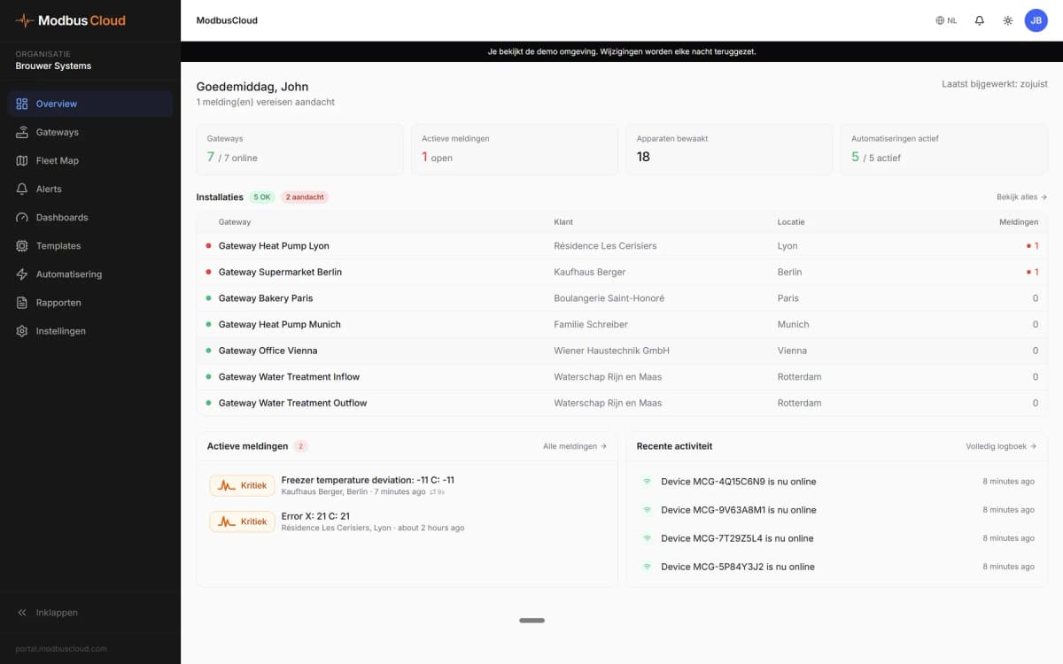
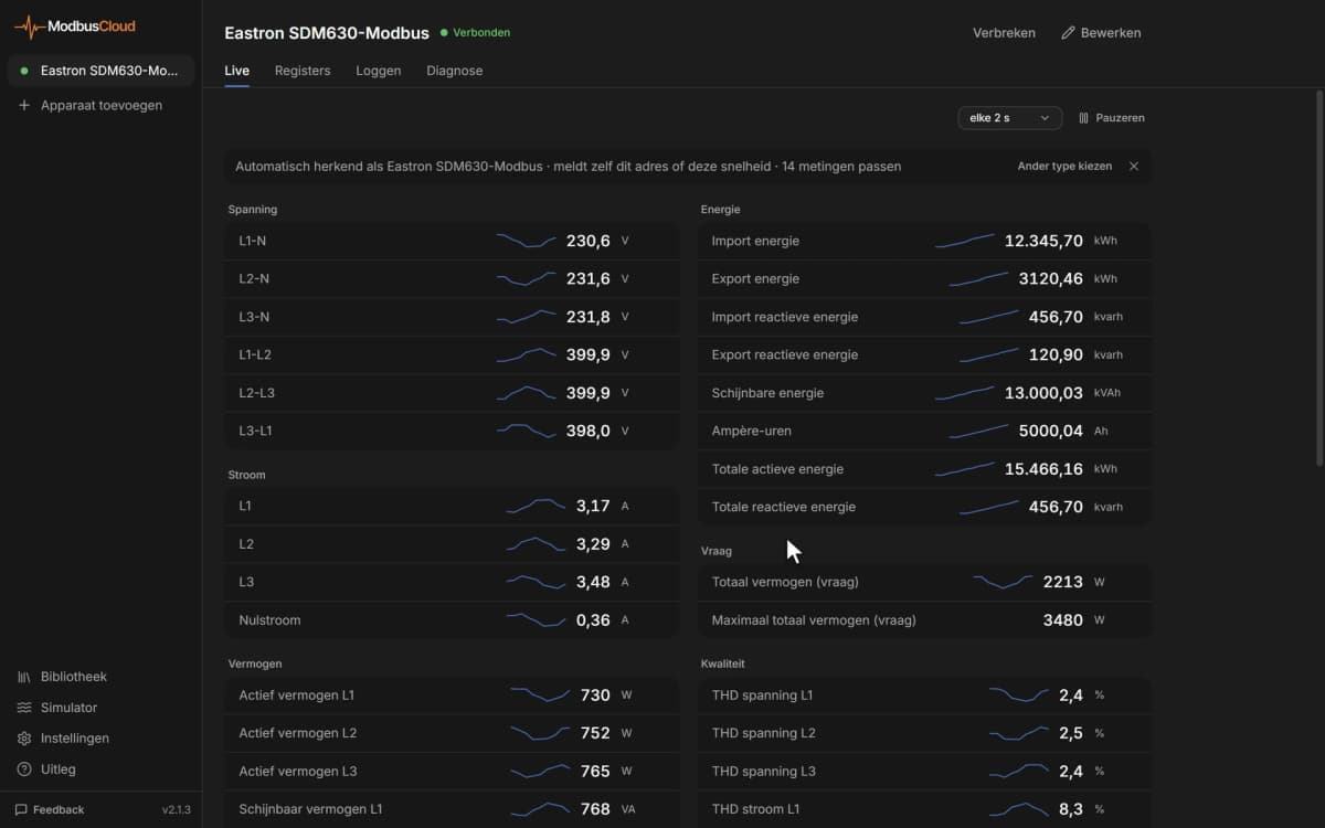
- Show frequency, motor current and power of every drive on one ModbusCloud dashboard.
- Get an email alert when the alarm word is not 0 or the heatsink temperature passes a set limit.
- Track running hours and energy per drive to plan maintenance and report consumption.
- Start, stop or change the speed of a conveyor or pump remotely from ModbusCloud.
- Compare ramp times, limits and motor data across drives without opening the cabinet.
Installation
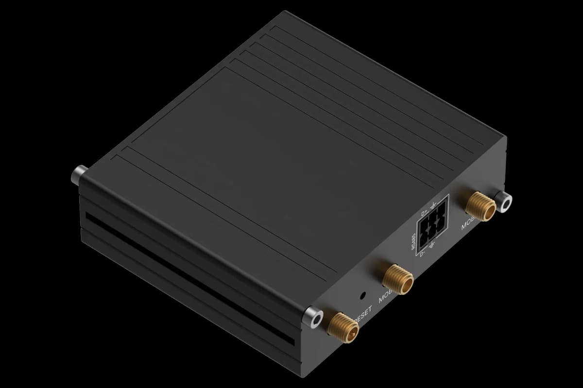
Connect terminals 68 (+) and 69 (-) of the drive to A and B of the ModbusCloud Gateway, with termination at the bus end (switch on the control card).
On the drive, set 8-30 Protocol to Modbus RTU, choose an address in 8-31 and set baud rate and parity in 8-32 and 8-33.
In ModbusCloud, add a Modbus RTU device with that address and these serial settings and import this template.
Check that Frequency (16-13) and Motor current (16-14) match the drive display.
Things to watch for
The drive does not answer. What should I check?
Check that 8-30 is set to Modbus RTU and not FC, that address, baud rate and parity in 8-31 to 8-33 match ModbusCloud, and that the drive was restarted or the change applied. Swap A and B if needed and switch on the bus termination at the last device.
Why are values ten or a hundred times too high?
Parameters are sent as whole numbers with a conversion index. The template already applies the factor, such as 0.01 for motor current. If you add registers by hand, use the conversion index of that parameter from the register comment.
How do I read an array parameter?
Array parameters, such as preset references or the alarm log, share one address. Write the wanted index to Index Pointer (holding register 9) first, then read or write the parameter.
Why does writing a start or speed command have no effect?
Check 8-01 Control Site and 8-50 to 8-56, which decide whether bus or terminals control the drive. Set the data valid bit (coil 11) together with the control word. Coil 65 decides whether parameter writes are kept in EEPROM; avoid frequent EEPROM writes.
Can I connect several drives to one bus?
Yes. Give each drive its own address in 8-31 and use the same baud rate and parity on all of them, then add each one in ModbusCloud as a separate device with this template.


Want to see how it works?