









Janitza UMG806
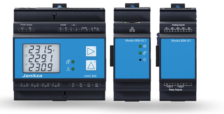
The Janitza UMG806 is a compact DIN rail power analyzer designed for sub-metering and energy monitoring in commercial and industrial installations. This Modbus RTU template reads per-phase voltage and current on L1, L2, and L3, active and reactive power per phase and as three-phase totals, grid frequency, and cumulative active energy for both consumption and production. Connecting the UMG806 via the ModbusCloud Gateway gives installers and facility managers continuous visibility into load balance, power quality trends, and import/export totals from a single cloud dashboard.
- Protocol
- Modbus RTU
- Connection
- RS485
- Registers
- 17, read only
- Brand
- Janitza
- Last updated
Registers (17)
17 read, 0 write
| Name | Unit | Access | Address (Hidden until you enter your email) | Function (hidden) | Type (hidden) |
|---|---|---|---|---|---|
| voltage_l1 | V | Read | |||
| voltage_l2 | V | Read | |||
| voltage_l3 | V | Read | |||
| current_l1 | A | Read | |||
| current_l2 | A | Read | |||
| current_l3 | A | Read | |||
| active_power_l1 | W | Read | |||
| active_power_l2 | W | Read | |||
| active_power_l3 | W | Read | |||
| active_power | W | Read | |||
| reactive_power_l1 | W | Read | |||
| reactive_power_l2 | W | Read | |||
| reactive_power_l3 | W | Read | |||
| reactive_power | var | Read | |||
| frequency | Hz | Read | |||
| active_consumption_energy | Wh | Read | |||
| active_production_energy | Wh | Read |
Loading registers…
Send your device list
If a device is not in the library yet, we build the template for free as soon as we have the register data.
Use cases
- Monitor per-phase active power on L1, L2, and L3 to detect load imbalances across distribution panels.
- Track cumulative active consumption and production energy to validate billing data against utility invoices.
- Alert on grid frequency deviations to identify unstable supply conditions before equipment is affected.
- Compare reactive power per phase over time to schedule power-factor correction capacitor maintenance.
- Verify that phase voltages stay within acceptable bounds during peak demand periods across multiple sites.
Installation
On the UMG806, navigate to the RS-485 communication settings using the front-panel buttons and set the Modbus slave address and baud rate; ensure all devices on the bus share the same baud rate (9600, 19200, 38400, 57600, or 115200 Bd).
Wire the RS-485 bus to the ModbusCloud Gateway using a shielded twisted-pair cable: connect terminal A on the UMG806 to terminal A on the Gateway and terminal B to terminal B; connect the cable shield to ground at one end only.
In the ModbusCloud portal, add the Gateway, import the Janitza UMG806 template, and assign the slave address configured on the device; set the matching baud rate and parity in the Gateway serial-port settings.
Confirm communication by checking the live value for voltage_l1 (address 19000) in the portal register view; a stable float32 reading near your nominal phase voltage confirms the connection is working.
Things to watch for
All register values show zero or NaN. What is wrong?
The UMG806 returns float32 values encoded as two consecutive 16-bit registers in big-endian word order. Confirm your Modbus master requests two registers per value starting at the correct address and interprets them as IEEE 754 float32 with high word first. A single-register read will always return an unusable result.
The gateway connects but no data appears after import.
Check that the slave address set on the UMG806 front panel matches the unit ID configured in the ModbusCloud portal exactly. Also verify the baud rate, parity, and stop bits on the Gateway serial port match the UMG806 settings; a single mismatch prevents all register reads even though the bus is physically wired correctly.
RS-485 communication drops intermittently on a multi-device bus.
Long RS-485 runs or buses with more than two devices often require 120-ohm termination resistors at each end of the cable. Make sure the cable shield is grounded at only one point. Reversed A/B polarity on any one device will corrupt traffic for all devices on the segment.
Active power reads in kilowatts but the unit field says W. Is that correct?
The Janitza Modbus address list documents the power registers as kW at the device level, but the OpenEMS template presents the values with a W unit field. Verify the actual magnitude of readings against a known load to confirm whether a scaling factor of 1000 is applied by the integration layer before the value reaches the portal.



Want to see how it works?
