

SATEC PM130 PLUS Setup
Configuration of a three-phase panel meter: ratios, demand, communication, clock, setpoints and I/O.
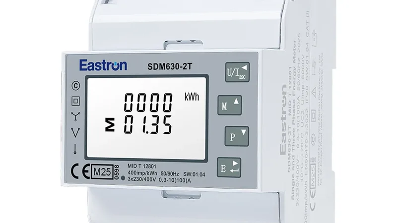
The SATEC PM130 PLUS is a three-phase panel meter for switchboards and substations with alarm setpoints, relay outputs and several communication options. This Modbus RTU template reads its identification and setup and lets you change transformer ratios, demand periods, setpoints, outputs, clock and communication settings from ModbusCloud.
- Protocol
- Modbus RTU
- Connection
- RS485, 19200 baud
- Registers
- 328, read and write
- Brand
- SATEC
- Key readings
- Model and firmware · Wiring mode · PT and CT ratio · Demand periods · Clock · Setpoint settings
- Available commands
- PT and CT ratio · Demand period · Alarm setpoints · Relay output mode · Clock and daylight saving · Communication settings
- Compatible models
- PM130P PLUS · PM130E PLUS · PM130EH PLUS
- Last updated
Registers (328)
328 read, 287 write
| Name | Unit | Access | Address (Hidden until you enter your email) | Function (hidden) | Type (hidden) |
|---|---|---|---|---|---|
| Device Serial Number | Read | 46080 | FC03 | uint32 | |
| Device Model ID | Read | 46082 | FC03 | uint32 | |
| Device Model Name | Read | 46084 | FC03 | string | |
| Device Options | Read | 46092 | FC03 | uint32 | |
| Firmware Version | Read | 46100 | FC03 | uint16 | |
| Firmware Build | Read | ||||
| Boot Loader Version | Read | ||||
| Boot Loader Build | Read | ||||
| Voltage Input Range | V | Read | |||
| Voltage Input Overload | % | Read | |||
| CT Type | Read | ||||
| Current Input Range | A | Read | |||
| Current Input Overload | % | Read | |||
| Ethernet MAC Address Bytes 0-1 | Read | ||||
| Ethernet MAC Address Bytes 2-3 | Read | ||||
| Ethernet MAC Address Bytes 4-5 | Read | ||||
| Wiring Mode | Read and write | ||||
| PT Ratio | Read and write | ||||
| CT Primary Current | A | Read and write | |||
| Power Block Demand Period | min | Read and write | |||
| Volt Ampere Demand Period | s | Read and write | |||
| Sliding Window Blocks | Read and write | ||||
| Nominal Line Frequency | Hz | Read and write | |||
| Maximum Demand Load Current | A | Read and write | |||
| PT Ratio Multiplication Factor | Read and write | ||||
| COM1 Protocol | Read and write | ||||
| COM1 Interface | Read and write | ||||
| COM1 Device Address | Read and write | ||||
| COM1 Baud Rate | Read and write | ||||
| COM1 Data Format | Read and write | ||||
| COM1 Flow Control | Read and write | ||||
| COM1 RTS Mode | Read and write | ||||
| COM1 ASCII Compatibility Mode | Read and write | ||||
| COM2 Protocol | Read and write | ||||
| COM2 Interface | Read and write | ||||
| COM2 Device Address | Read and write | ||||
| COM2 Baud Rate | Read and write | ||||
| COM2 Data Format | Read and write | ||||
| COM2 Flow Control | Read and write | ||||
| COM2 RTS Mode | Read and write | ||||
| COM2 ASCII Compatibility Mode | Read and write | ||||
| Power Calculation Mode | Read and write | ||||
| Energy Roll Value | Read and write | ||||
| Phase Energy Calculation Mode | Read and write | ||||
| Energy Pulse Resolution | Read and write | ||||
| Energy LED Test Mode | Read and write | ||||
| Starting Voltage | % | Read and write | |||
| Device Resolution | Read and write | ||||
| AC DC Mode | Read and write | ||||
| DST Option | Read and write | ||||
| DST Start Month | Read and write | ||||
| DST Start Week | Read and write | ||||
| DST Start Weekday | Read and write | ||||
| DST End Month | Read and write | ||||
| DST End Week | Read and write | ||||
| DST End Weekday | Read and write | ||||
| Clock Synchronization Source | Read and write | ||||
| Country Code | Read and write | ||||
| DST Start Hour | Read and write | ||||
| DST End Hour | Read and write | ||||
| Clock Seconds | Read and write | ||||
| Clock Minutes | Read and write | ||||
| Clock Hour | Read and write | ||||
| Clock Day of Month | Read and write | ||||
| Clock Month | Read and write | ||||
| Clock Year | Read and write | ||||
| Clock Weekday | Read and write | ||||
| Setpoint 1 Trigger Parameter | Read and write | ||||
| Setpoint 1 Action | Read and write | ||||
| Setpoint 1 Operate Delay | s | Read and write | |||
| Setpoint 1 Release Delay | s | Read and write | |||
| Setpoint 1 Operate Limit | Read and write | ||||
| Setpoint 1 Release Limit | Read and write | ||||
| Setpoint 2 Trigger Parameter | Read and write | ||||
| Setpoint 2 Action | Read and write | ||||
| Setpoint 2 Operate Delay | s | Read and write | |||
| Setpoint 2 Release Delay | s | Read and write | |||
| Setpoint 2 Operate Limit | Read and write | ||||
| Setpoint 2 Release Limit | Read and write | ||||
| Setpoint 3 Trigger Parameter | Read and write | ||||
| Setpoint 3 Action | Read and write | ||||
| Setpoint 3 Operate Delay | s | Read and write | |||
| Setpoint 3 Release Delay | s | Read and write | |||
| Setpoint 3 Operate Limit | Read and write | ||||
| Setpoint 3 Release Limit | Read and write | ||||
| Setpoint 4 Trigger Parameter | Read and write | ||||
| Setpoint 4 Action | Read and write | ||||
| Setpoint 4 Operate Delay | s | Read and write | |||
| Setpoint 4 Release Delay | s | Read and write | |||
| Setpoint 4 Operate Limit | Read and write | ||||
| Setpoint 4 Release Limit | Read and write | ||||
| Setpoint 5 Trigger Parameter | Read and write | ||||
| Setpoint 5 Action | Read and write | ||||
| Setpoint 5 Operate Delay | s | Read and write | |||
| Setpoint 5 Release Delay | s | Read and write | |||
| Setpoint 5 Operate Limit | Read and write | ||||
| Setpoint 5 Release Limit | Read and write | ||||
| Setpoint 6 Trigger Parameter | Read and write | ||||
| Setpoint 6 Action | Read and write | ||||
| Setpoint 6 Operate Delay | s | Read and write | |||
| Setpoint 6 Release Delay | s | Read and write | |||
| Setpoint 6 Operate Limit | Read and write | ||||
| Setpoint 6 Release Limit | Read and write | ||||
| Setpoint 7 Trigger Parameter | Read and write | ||||
| Setpoint 7 Action | Read and write | ||||
| Setpoint 7 Operate Delay | s | Read and write | |||
| Setpoint 7 Release Delay | s | Read and write | |||
| Setpoint 7 Operate Limit | Read and write | ||||
| Setpoint 7 Release Limit | Read and write | ||||
| Setpoint 8 Trigger Parameter | Read and write | ||||
| Setpoint 8 Action | Read and write | ||||
| Setpoint 8 Operate Delay | s | Read and write | |||
| Setpoint 8 Release Delay | s | Read and write | |||
| Setpoint 8 Operate Limit | Read and write | ||||
| Setpoint 8 Release Limit | Read and write | ||||
| Setpoint 9 Trigger Parameter | Read and write | ||||
| Setpoint 9 Action | Read and write | ||||
| Setpoint 9 Operate Delay | s | Read and write | |||
| Setpoint 9 Release Delay | s | Read and write | |||
| Setpoint 9 Operate Limit | Read and write | ||||
| Setpoint 9 Release Limit | Read and write | ||||
| Setpoint 10 Trigger Parameter | Read and write | ||||
| Setpoint 10 Action | Read and write | ||||
| Setpoint 10 Operate Delay | s | Read and write | |||
| Setpoint 10 Release Delay | s | Read and write | |||
| Setpoint 10 Operate Limit | Read and write | ||||
| Setpoint 10 Release Limit | Read and write | ||||
| Setpoint 11 Trigger Parameter | Read and write | ||||
| Setpoint 11 Action | Read and write | ||||
| Setpoint 11 Operate Delay | s | Read and write | |||
| Setpoint 11 Release Delay | s | Read and write | |||
| Setpoint 11 Operate Limit | Read and write | ||||
| Setpoint 11 Release Limit | Read and write | ||||
| Setpoint 12 Trigger Parameter | Read and write | ||||
| Setpoint 12 Action | Read and write | ||||
| Setpoint 12 Operate Delay | s | Read and write | |||
| Setpoint 12 Release Delay | s | Read and write | |||
| Setpoint 12 Operate Limit | Read and write | ||||
| Setpoint 12 Release Limit | Read and write | ||||
| Setpoint 13 Trigger Parameter | Read and write | ||||
| Setpoint 13 Action | Read and write | ||||
| Setpoint 13 Operate Delay | s | Read and write | |||
| Setpoint 13 Release Delay | s | Read and write | |||
| Setpoint 13 Operate Limit | Read and write | ||||
| Setpoint 13 Release Limit | Read and write | ||||
| Setpoint 14 Trigger Parameter | Read and write | ||||
| Setpoint 14 Action | Read and write | ||||
| Setpoint 14 Operate Delay | s | Read and write | |||
| Setpoint 14 Release Delay | s | Read and write | |||
| Setpoint 14 Operate Limit | Read and write | ||||
| Setpoint 14 Release Limit | Read and write | ||||
| Setpoint 15 Trigger Parameter | Read and write | ||||
| Setpoint 15 Action | Read and write | ||||
| Setpoint 15 Operate Delay | s | Read and write | |||
| Setpoint 15 Release Delay | s | Read and write | |||
| Setpoint 15 Operate Limit | Read and write | ||||
| Setpoint 15 Release Limit | Read and write | ||||
| Setpoint 16 Trigger Parameter | Read and write | ||||
| Setpoint 16 Action | Read and write | ||||
| Setpoint 16 Operate Delay | s | Read and write | |||
| Setpoint 16 Release Delay | s | Read and write | |||
| Setpoint 16 Operate Limit | Read and write | ||||
| Setpoint 16 Release Limit | Read and write | ||||
| Counter 1 Source Input | Read and write | ||||
| Counter 1 Multiplier | Read and write | ||||
| Counter 2 Source Input | Read and write | ||||
| Counter 2 Multiplier | Read and write | ||||
| Counter 3 Source Input | Read and write | ||||
| Counter 3 Multiplier | Read and write | ||||
| Counter 4 Source Input | Read and write | ||||
| Counter 4 Multiplier | Read and write | ||||
| AO1 Output Parameter | Read and write | ||||
| AO1 Zero Scale | Read and write | ||||
| AO1 Full Scale | Read and write | ||||
| AO2 Output Parameter | Read and write | ||||
| AO2 Zero Scale | Read and write | ||||
| AO2 Full Scale | Read and write | ||||
| Device IP Address | Read and write | ||||
| Network Subnet Mask | Read and write | ||||
| Network Default Gateway | Read and write | ||||
| Use DHCP | Read and write | ||||
| TCP Service Port | Read and write | ||||
| WiFi Station SSID | Read and write | ||||
| WiFi Station Security Type | Read and write | ||||
| WiFi Station Security Key | Read and write | ||||
| WiFi Access Point Enable | Read and write | ||||
| WiFi Protocol | Read and write | ||||
| WiFi Access Point LAN IP Address | Read and write | ||||
| WiFi Access Point LAN Subnet Mask | Read and write | ||||
| WiFi Access Point SSID | Read and write | ||||
| WiFi Access Point Security Type | Read and write | ||||
| WiFi Access Point Security Key | Read and write | ||||
| WiFi Channel | Read and write | ||||
| Communications Password | Read and write | ||||
| Password Protection | Read and write | ||||
| Expert Power Server IP Address | Read and write | ||||
| Expert Power Server Port | Read and write | ||||
| Expert Power Client Enabled | Read and write | ||||
| Expert Power Time to Next Session | min | Read and write | |||
| Expert Power Time to Next Session Readback | min | Read | |||
| ISP Telephone Number | Read and write | ||||
| ISP Login Name | Read and write | ||||
| ISP Login Password | Read and write | ||||
| GPRS Access Point Name | Read and write | ||||
| GPRS User Name | Read and write | ||||
| GPRS Password | Read and write | ||||
| Notification Client Enabled | Read and write | ||||
| Notification Server Address | Read and write | ||||
| Notification Server Port | Read and write | ||||
| Notification Message Exchange Address | Read and write | ||||
| V1 Ratio Correction Factor | Read and write | ||||
| V1 Phase Angle Error | min | Read and write | |||
| V2 Ratio Correction Factor | Read and write | ||||
| V2 Phase Angle Error | min | Read and write | |||
| V3 Ratio Correction Factor | Read and write | ||||
| V3 Phase Angle Error | min | Read and write | |||
| I1 Ratio Correction Factor | Read and write | ||||
| I1 Phase Angle Error | min | Read and write | |||
| I2 Ratio Correction Factor | Read and write | ||||
| I2 Phase Angle Error | min | Read and write | |||
| I3 Ratio Correction Factor | Read and write | ||||
| I3 Phase Angle Error | min | Read and write | |||
| Summary Register 1 Units | Read and write | ||||
| Summary Register 1 Flags | Read and write | ||||
| Summary Register 2 Units | Read and write | ||||
| Summary Register 2 Flags | Read and write | ||||
| Summary Register 3 Units | Read and write | ||||
| Summary Register 3 Flags | Read and write | ||||
| Summary Register 4 Units | Read and write | ||||
| Summary Register 4 Flags | Read and write | ||||
| Energy Source 1 ID | Read and write | ||||
| Energy Source 1 Target Register | Read and write | ||||
| Energy Source 1 Multiplier | Read and write | ||||
| Energy Source 2 ID | Read and write | ||||
| Energy Source 2 Target Register | Read and write | ||||
| Energy Source 2 Multiplier | Read and write | ||||
| Energy Source 3 ID | Read and write | ||||
| Energy Source 3 Target Register | Read and write | ||||
| Energy Source 3 Multiplier | Read and write | ||||
| Energy Source 4 ID | Read and write | ||||
| Energy Source 4 Target Register | Read and write | ||||
| Energy Source 4 Multiplier | Read and write | ||||
| DI1 Pulse Mode | Read and write | ||||
| DI1 Polarity | Read and write | ||||
| DI1 Debounce Time | ms | Read and write | |||
| DI2 Pulse Mode | Read and write | ||||
| DI2 Polarity | Read and write | ||||
| DI2 Debounce Time | ms | Read and write | |||
| DI3 Pulse Mode | Read and write | ||||
| DI3 Polarity | Read and write | ||||
| DI3 Debounce Time | ms | Read and write | |||
| DI4 Pulse Mode | Read and write | ||||
| DI4 Polarity | Read and write | ||||
| DI4 Debounce Time | ms | Read and write | |||
| DI5 Pulse Mode | Read and write | ||||
| DI5 Polarity | Read and write | ||||
| DI5 Debounce Time | ms | Read and write | |||
| DI6 Pulse Mode | Read and write | ||||
| DI6 Polarity | Read and write | ||||
| DI6 Debounce Time | ms | Read and write | |||
| DI7 Pulse Mode | Read and write | ||||
| DI7 Polarity | Read and write | ||||
| DI7 Debounce Time | ms | Read and write | |||
| DI8 Pulse Mode | Read and write | ||||
| DI8 Polarity | Read and write | ||||
| DI8 Debounce Time | ms | Read and write | |||
| DI9 Pulse Mode | Read and write | ||||
| DI9 Polarity | Read and write | ||||
| DI9 Debounce Time | ms | Read and write | |||
| DI10 Pulse Mode | Read and write | ||||
| DI10 Polarity | Read and write | ||||
| DI10 Debounce Time | ms | Read and write | |||
| DI11 Pulse Mode | Read and write | ||||
| DI11 Polarity | Read and write | ||||
| DI11 Debounce Time | ms | Read and write | |||
| DI12 Pulse Mode | Read and write | ||||
| DI12 Polarity | Read and write | ||||
| DI12 Debounce Time | ms | Read and write | |||
| RO1 Operation Mode | Read and write | ||||
| RO1 Polarity | Read and write | ||||
| RO1 Pulse Width | ms | Read and write | |||
| RO1 Pulse Source | Read and write | ||||
| RO1 Units per Pulse | Read and write | ||||
| RO2 Operation Mode | Read and write | ||||
| RO2 Polarity | Read and write | ||||
| RO2 Pulse Width | ms | Read and write | |||
| RO2 Pulse Source | Read and write | ||||
| RO2 Units per Pulse | Read and write | ||||
| RO3 Operation Mode | Read and write | ||||
| RO3 Polarity | Read and write | ||||
| RO3 Pulse Width | ms | Read and write | |||
| RO3 Pulse Source | Read and write | ||||
| RO3 Units per Pulse | Read and write | ||||
| RO4 Operation Mode | Read and write | ||||
| RO4 Polarity | Read and write | ||||
| RO4 Pulse Width | ms | Read and write | |||
| RO4 Pulse Source | Read and write | ||||
| RO4 Units per Pulse | Read and write | ||||
| AO1 Output Parameter 32-bit Setup | Read and write | ||||
| AO1 Zero Scale 32-bit | Read and write | ||||
| AO1 Full Scale 32-bit | Read and write | ||||
| AO2 Output Parameter 32-bit Setup | Read and write | ||||
| AO2 Zero Scale 32-bit | Read and write | ||||
| AO2 Full Scale 32-bit | Read and write | ||||
| DI Slot IO Type | Read | ||||
| DI Slot Number of IOs | Read | ||||
| DI Slot First IO Number | Read | ||||
| DI Slot Last IO Number | Read | ||||
| RO Slot IO Type | Read | ||||
| RO Slot Number of IOs | Read | ||||
| RO Slot First IO Number | Read | ||||
| RO Slot Last IO Number | Read | ||||
| AIAO Slot IO Type | Read | ||||
| AIAO Slot Number of IOs | Read | ||||
| AIAO Slot First IO Number | Read | ||||
| AIAO Slot Last IO Number | Read | ||||
| DI Number of Slots | Read | ||||
| DI Total IOs | Read | ||||
| DI IOs on Slot | Read | ||||
| RO Number of Slots | Read | ||||
| RO Total IOs | Read | ||||
| RO IOs on Slot | Read | ||||
| AI Number of Slots | Read | ||||
| AI Total IOs | Read | ||||
| AI IOs on Slot | Read | ||||
| AO Number of Slots | Read | ||||
| AO Total IOs | Read | ||||
| AO IOs on Slot | Read |
Loading registers…
Send your device list
If a device is not in the library yet, we build the template for free as soon as we have the register data.
Use cases
- Check after commissioning that the PT and CT ratio and the wiring mode of every meter in a substation are set the same.
- Set an alarm setpoint and its relay action on the meter from ModbusCloud without going to site.
- Change the demand period of all meters to match the contract of the grid operator.
- Correct the meter clock and daylight saving so that logged maximum demands carry the right time.
- Keep the firmware version of each meter in view on a dashboard before a service visit.
Installation
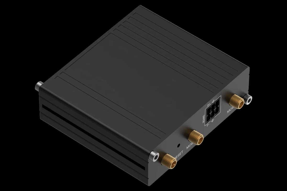
Wire the RS485 port of the PM130 PLUS to the ModbusCloud Gateway, A to A and B to B, with termination at the end of the bus.
Check the Modbus address, baud rate and data format of COM1 in the meter setup menu.
In ModbusCloud add a Modbus device on the Gateway with the same address as the main PM130 PLUS template, and import this template.
Check that the model name, firmware version and PT and CT ratio read correctly before you write any setting.
Things to watch for
Why does the meter refuse a setting I write?
When password protection is on, the meter only accepts setup writes after the communications password is entered. Write the password through the control and status template first, then write the setting.
What should I watch out for when writing settings?
Settings change how the meter measures and talks. Read the current value first and write one block at a time. SATEC recommends writing a whole setup block in one request, or clearing it first.
Why do the setpoint limits look far too large or small?
Operate and release limits use the same scaled values as the 16-bit register set of section 3.3 for the chosen trigger parameter. Convert the engineering value with the scale of that parameter before you write the limit.
Why do COM1 Flow Control and RTS Mode read 65535?
These two settings only apply to COM2. On COM1, which is always RS-485, they do not apply and the meter returns 65535 for them.


Want to see how it works?