









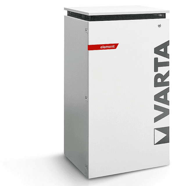
VARTA element backup (grid)
The VARTA element backup is a residential AC-coupled battery storage system available in the pulse, pulse neo, element, and element backup variants. It connects to the household grid connection point and uses an integrated current sensor to measure power flow. This Modbus TCP template reads register 1078, the signed grid power value, which reports watts flowing to or from the grid in real time. Positive values indicate backfeed; negative values indicate grid consumption. Connecting the ModbusCloud Gateway to the VARTA element backup lets you log, trend, and alert on grid exchange from a single cloud portal.
- Protocol
- Modbus TCP
- Connection
- Ethernet, Modbus TCP
- Registers
- 1, read only
- Brand
- VARTA
- Compatible models
- pulse · pulse neo · element · element backup
- Last updated
Registers (1)
1 read, 0 write
| Name | Unit | Access | Address (Hidden until you enter your email) | Function (hidden) | Type (hidden) |
|---|---|---|---|---|---|
| power | W | Read |
Loading registers…
Send your device list
If a device is not in the library yet, we build the template for free as soon as we have the register data.
Use cases
- Monitor real-time grid power to verify the battery is reducing grid consumption during peak evening hours.
- Track backfeed into the grid to confirm solar surplus is being exported rather than curtailed.
- Alert on sustained grid consumption above a threshold to detect unexpected battery underperformance.
- Compare grid power readings over multiple days to identify changes in household load patterns.
- Report daily net grid exchange to building owners as part of a monthly energy performance summary.
Installation
Confirm that Modbus TCP is active on the VARTA element backup: open the device web interface and check the communication or Modbus section; the default port is 502 and unit ID 255 is recommended.
Connect the ModbusCloud Gateway to the same local area network as the VARTA device, ensuring the Gateway can reach the battery system's IP address on port 502.
In the ModbusCloud portal, add a new device, import the VARTA element backup (grid) template, and assign the correct IP address and unit ID matching your installation.
Spot-check register 1078 in the live register view: with the grid supplying load you should see a negative watt value; with solar surplus active you should see a positive value.
Things to watch for
Register 1078 always returns zero. What is wrong?
The VARTA Modbus server only reflects sensor data after the internal current transformer at the grid connection point is correctly clipped and calibrated. Verify the sensor is physically installed and that the device web interface shows non-zero grid power in its own dashboard before polling over Modbus.
The Gateway connects but no values appear in the portal. What now?
VARTA devices allow only one active Modbus TCP client session at a time. If another system such as a home automation controller or energy management system is holding an open connection, the Gateway will be refused. Close or pause competing clients, then re-poll. A polling interval of one second or less keeps the connection stable.
Values appear but the sign seems inverted. Is my wiring wrong?
Register 1078 is a signed int16: positive means power flowing into the grid (backfeed), negative means power drawn from the grid. If the sign is opposite to your expectations, check that the current transformer at the grid connection point is clipped in the correct orientation as specified in the VARTA installation guide.
I get an illegal data address error when polling. How do I fix this?
Some Modbus clients prepend a leading digit to register addresses, resulting in address 41078 instead of 1078. Use the bare address 1078 with function code 3 (read holding registers). Also confirm the unit ID matches the device setting, with 255 being the default recommended by VARTA.
Want to see how it works?
