

Wilo Stratos GIGA2.0
Inline circulation pump for heating, cooling and air conditioning with values, errors and control over Modbus RTU.
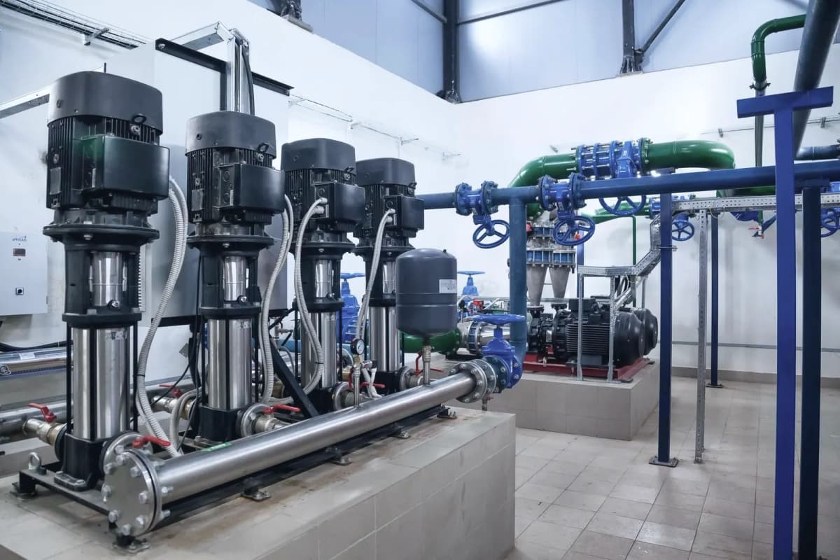
The Wilo Stratos GIGA2.0 is a high-efficiency inline pump that circulates water in heating, cooling and air conditioning systems of larger buildings. This Modbus RTU template reads pressure, flow, power, energy, speed, error codes and heat meter values, and lets you set the duty point, control mode and on and off command from ModbusCloud.
- Protocol
- Modbus RTU
- Connection
- RS485, 9600 baud
- Registers
- 124, read and write
- Brand
- Wilo
- Key readings
- Pressure · Flow · Power input · Energy consumption · Speed · Error code · Heating and cooling energy · Flow and return temperature
- Available commands
- Pump on and off · Duty point · Control mode · Setpoint source · PID controller settings · Flow limits
- Compatible models
- Stratos GIGA2.0-I · Stratos GIGA2.0-D
- Last updated
Registers (124)
124 read, 26 write
| Name | Unit | Access | Address (Hidden until you enter your email) | Function (hidden) | Type (hidden) |
|---|---|---|---|---|---|
| Duty Point Setpoint | % | Read and write | 1 | FC03 / FC06 | int16 |
| Pump Command | Read and write | 40 | FC03 / FC06 | uint16 | |
| Control Mode Setpoint | Read and write | 42 | FC03 / FC06 | uint16 | |
| Bus Command Timer | Read and write | 300 | FC03 / FC06 | uint16 | |
| Reference Temperature T1 Setpoint | K | Read and write | 302 | FC03 / FC16 | float32 |
| Reference Temperature T2 Setpoint | K | Read and write | |||
| Sensor Signal Input | Read and write | ||||
| Bus Command Timer Timeout | s | Read and write | |||
| Setpoint Source Setting | Read and write | ||||
| Duty Point Preset | % | Read and write | |||
| Control Mode Preset | Read and write | ||||
| Pump Command Preset | Read and write | ||||
| Setpoint Source Preset | Read and write | ||||
| PID Gain Kp | Read and write | ||||
| PID Integral Time Ti | s | Read and write | |||
| PID Derivative Time Td | s | Read and write | |||
| Duty Point Aux | % | Read and write | |||
| Control Mode Aux | Read and write | ||||
| Pump Command Aux | Read and write | ||||
| Setpoint Source Aux | Read and write | ||||
| Parameter Set Selection | Read and write | ||||
| Flow Limit Max Setting | m³/h | Read and write | |||
| Flow Limit Min Setting | m³/h | Read and write | |||
| Flow Limit Off Setting | m³/h | Read and write | |||
| Zero Flow Setpoint Reduction Setting | % | Read and write | |||
| Nominal Flow For Control Setting | m³/h | Read and write | |||
| Pressure | Read | ||||
| Flow | m³/h | Read | |||
| Energy Consumption | kWh | Read | |||
| Power Input | W | Read | |||
| Operation Time | h | Read | |||
| Speed | rpm | Read | |||
| Operating Hours Double Pump | h | Read | |||
| Active Control Mode | Read | ||||
| Pump Module Type | Read | ||||
| Pump Type PLR | Read | ||||
| Maximum Speed | rpm | Read | |||
| Minimum Speed | rpm | Read | |||
| Max Pressure Setpoint Dp-c | Read | ||||
| Min Pressure Setpoint Dp-c | Read | ||||
| Max Pressure Setpoint Dp-v | Read | ||||
| Min Pressure Setpoint Dp-v | Read | ||||
| Maximum Flow | m³/h | Read | |||
| Minimum Flow | m³/h | Read | |||
| Maximum Power Input | W | Read | |||
| Service Message | Read | ||||
| Error Type | Read | ||||
| Error Message Bits | Read | ||||
| Pump Status | Read | ||||
| State Diagnostics | Read | ||||
| Slave Pump Module Type | Read | ||||
| Slave Pump Type PLR | Read | ||||
| Slave Error Type | Read | ||||
| Slave Pump Status | Read | ||||
| Duty Point | % | Read | |||
| Duty Point Active Max | % | Read | |||
| Duty Point Active Min | % | Read | |||
| Duty Point 100 Percent Value | Read | ||||
| Duty Point Unit Code | Read | ||||
| Active Setpoint Source | Read | ||||
| Active Parameter Set | Read | ||||
| Maximum Pressure | bar | Read | |||
| Duty Point Input Max | % | Read | |||
| Duty Point Input Min | % | Read | |||
| Duty Point Input 100 Percent Value | Read | ||||
| Duty Point Input Unit Code | Read | ||||
| Duty Point Aux Max | % | Read | |||
| Duty Point Aux Min | % | Read | |||
| Duty Point Aux 100 Percent Value | Read | ||||
| Duty Point Aux Unit Code | Read | ||||
| Duty Point Preset Max | % | Read | |||
| Duty Point Preset Min | % | Read | |||
| Duty Point Preset 100 Percent Value | Read | ||||
| Duty Point Preset Unit Code | Read | ||||
| Selected Duty Point | % | Read | |||
| Selected Duty Point Max | % | Read | |||
| Selected Duty Point Min | % | Read | |||
| Selected Duty Point 100 Percent Value | Read | ||||
| Selected Duty Point Unit Code | Read | ||||
| Selected Control Mode | Read | ||||
| Selected Pump Command | Read | ||||
| Selected Setpoint Source | Read | ||||
| Active Flow Limit Max | m³/h | Read | |||
| Active Flow Limit Min | m³/h | Read | |||
| Active Flow Limit Off | m³/h | Read | |||
| Active Zero Flow Setpoint Reduction | % | Read | |||
| Active Nominal Flow For Control | m³/h | Read | |||
| Heating Power | W | Read | |||
| Cooling Power | W | Read | |||
| Heating Energy Resettable | kWh | Read | |||
| Heating Energy Reset Time | Read | ||||
| Cooling Energy Resettable | kWh | Read | |||
| Cooling Energy Reset Time | Read | ||||
| Heating Energy Total | kWh | Read | |||
| Cooling Energy Total | kWh | Read | |||
| Flow Temperature | K | Read | |||
| Return Temperature | K | Read | |||
| Input Voltage | V | Read | |||
| Analog Input 1 Value | Read | ||||
| Analog Input 2 Value | Read | ||||
| Analog Input 1 Unit Code | Read | ||||
| Analog Input 2 Unit Code | Read | ||||
| Reference Temperature T1 | K | Read | |||
| Reference Temperature T2 | K | Read | |||
| Analog Input 3 Value | Read | ||||
| Analog Input 4 Value | Read | ||||
| Analog Input 3 Unit Code | Read | ||||
| Analog Input 4 Unit Code | Read | ||||
| Sensor Signal | Read | ||||
| Duty Point Output | % | Read | |||
| Active Pump Command | Read | ||||
| Pump Command Output | Read | ||||
| Operation Status | Read | ||||
| Heartbeat Count | Read | ||||
| System Time | s | Read | |||
| Bus Command Timer Remaining | s | Read | |||
| CIF Firmware Version | Read | ||||
| Vendor ID | Read | ||||
| Software Build ID | Read | ||||
| Pump Type CAN | Read | ||||
| Slave Pump Type CAN | Read | ||||
| User Trouble Code | Read | ||||
| Error Code | Read | ||||
| Slave Error Code | Read |
Loading registers…
Send your device list
If a device is not in the library yet, we build the template for free as soon as we have the register data.
Use cases
- Get an alert when the error code is not 0 and see the Wilo text, such as dry running or a blocked rotor, before you go on site.
- Log power input and energy consumption per pump to find pumps that run at high load at night.
- Compare flow and pressure with the design point to check whether a heating or cooling circuit is balanced.
- Report heating and cooling energy per circuit from the heat meter values on a dashboard.
- Change the duty point or switch the pump off remotely from ModbusCloud, for example outside office hours.
Installation
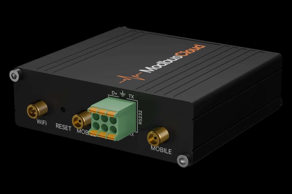
Fit the CIF-Module Modbus RTU in the pump and connect RS485 A and B to the ModbusCloud Gateway; switch on the termination at the end of the line.
In the pump menu set the Modbus address, the baud rate and the frame, for example address 1, 9600 baud and 8N1.
In ModbusCloud, add a Modbus device (RTU) with the same address and serial settings, then import this template.
Check that power input and speed show plausible values while the pump runs; if nothing answers, check address, baud rate and A and B.
Before you write a duty point or command, read the current values so you know the starting point.
Things to watch for
The pump does not answer on the bus. What should I check?
The CIF module uses the address, baud rate and frame set in the pump menu; there is no fixed default. Compare them with the device in ModbusCloud, for example 1, 9600 baud and 8N1. Swap A and B if nothing answers, check the termination at both ends of the line and make sure there is only one master on the bus.
Some registers give an error or no value. Why?
Duty point, heat meter values, temperatures, voltage and the auxiliary parameter set need a recent CIF module firmware. Read the CIF firmware version: the main version is in the highest byte. With an older module only the basic values such as pressure, flow, power and the error code are available.
Why does the temperature show 330 instead of 57?
The pump reports flow and return temperature in kelvin. A value of 330.0 K is 56.85 °C; subtract 273.15 to get degrees Celsius.
Pressure looks 10 times too high. Is that right?
The pump reports pressure in cm of water column. The template applies the factor 10, so 500 means 500 cm, about 0.49 bar. A raw value of 65535 means the pressure is not available.
I write a duty point but the pump does not follow it. What is wrong?
The pump only follows the bus when the setpoint source is the CIF module and no local override or external off input is active. The pump command also needs bit 3 set and bits 6 and 7 cleared when you write it. Read the active control mode, setpoint source and pump status first, and change one value at a time.

Want to see how it works?