

ABB Emax 2 Ekip Touch
Air circuit breaker trip unit that reports status, trips, currents, voltages, power and energy of an Emax 2.
The ABB Emax 2 Ekip Touch is the electronic trip unit of SACE Emax 2 air circuit breakers that protects main and sub-distribution and measures current, voltage, power and energy. This Modbus RTU template reads breaker status, trip and alarm words, measurements, harmonics and counters, and lets you send open, close and reset commands from ModbusCloud.
- Protocol
- Modbus RTU
- Connection
- RS485, 19200 baud
- Registers
- 265, read and write
- Brand
- ABB
- Key readings
- Breaker status · Phase currents · Voltages · Active power · Active energy · Power factor · Harmonic distortion · Operation counters
- Available commands
- Open and close breaker · Trip reset · Clock
- Compatible models
- Ekip Touch · Ekip Hi-Touch · Ekip G Touch · Ekip LCD · ABB SACE Emax 2 E1.2, E2.2, E4.2 and E6.2 with Ekip Com Modbus RTU, trip unit firmware 3.xx
- Last updated
Registers (265)
265 read, 4 write
| Name | Unit | Access | Address (Hidden until you enter your email) | Function (hidden) | Type (hidden) |
|---|---|---|---|---|---|
| Command (type+parameter) | Read and write | ||||
| Seconds Low | Read and write | ||||
| Seconds High | Read and write | ||||
| Milliseconds | ms | Read and write | |||
| Contact Wear | % | Read | |||
| Nr of CB operations | Read | ||||
| Nr of CB manual openings | Read | ||||
| Nr of CB protection trips | Read | ||||
| Nr of CB protection trip fails | Read | ||||
| Nr of CB protection trip test | Read | ||||
| Programming Fail error code | Read | ||||
| Status Global 1 | Read | ||||
| Status Global 2 | Read | ||||
| Status Glitch 1 | Read | ||||
| Status Glitch 2 | Read | ||||
| Status Flags 1 | Read | ||||
| Status Flags 2 | Read | ||||
| Status Accessories 1 | Read | ||||
| Status Accessories 2 | Read | ||||
| Status Timing 1 | Read | ||||
| Status Timing 2 | Read | ||||
| Status Trips 1 (Latched) | Read | ||||
| Status Trips 2 (Latched) | Read | ||||
| Status Trips 3 (Latched) | Read | ||||
| Status Warnings Alarms 1 | Read | ||||
| Status Warnings Alarms 2 | Read | ||||
| Status Warnings Alarms 3 | Read | ||||
| Status Warnings Alarms 4 | Read | ||||
| Status Warnings Alarms 5 | Read | ||||
| Status Warnings Alarms 6 | Read | ||||
| Status Ekip Signalling 4K + Local I/O | Read | ||||
| Status Ekip Signalling 10K input A | Read | ||||
| Status Ekip Signalling 10K input B | Read | ||||
| Status Ekip Signalling 2K input | Read | ||||
| Status Ekip Signalling 10K output A | Read | ||||
| Status Ekip Signalling 10K output B | Read | ||||
| Status Ekip Signalling 2K output | Read | ||||
| Status | Read | ||||
| Programmable Status | Read | ||||
| Ekip Link Actors Status | Read | ||||
| Load Output Status | Read | ||||
| Status ZS IN Remote | Read | ||||
| Status ZS OUT Remote | Read | ||||
| Accessories3 | Read | ||||
| Remote Programmable Status Bits | Read | ||||
| Remote Actor Selected Status Register A | Read | ||||
| Remote Actor Selected Status Register B | Read | ||||
| Remote Actor Selected Status Register C | Read | ||||
| Remote Actor Selected Status Register D | Read | ||||
| Zone Selectivity Protection Status | Read | ||||
| Ekip Signalling 3T 1 Protection Status | Read | ||||
| Status Flags 3 | Read | ||||
| Status Warnings Alarms 7 | Read | ||||
| Status Warnings Alarms 8 | Read | ||||
| Status 83 | Read | ||||
| Status Timing 4 | Read | ||||
| Status Trips 4 (Latched) | Read | ||||
| L1 current (Legacy) | A | Read | |||
| L2 current (Legacy) | A | Read | |||
| L3 current (Legacy) | A | Read | |||
| Ne current (Legacy) | A | Read | |||
| Internal ground current (Legacy) | A | Read | |||
| External ground current/Rc current | A | Read | |||
| Maximum current (Legacy) | A | Read | |||
| Maximum current phase (Legacy) | Read | ||||
| L1 min Current Value (Standard) | A | Read | |||
| Timestamp of L1 Min Current Value (Standard) [s] | s | Read | |||
| L1 max Current Value (Standard) | A | Read | |||
| Timestamp of L1 max Current Value (Standard) [s] | s | Read | |||
| L2 min Current Value (Standard) | A | Read | |||
| Timestamp of L2 Min Current Value (Standard) [s] | s | Read | |||
| L2 max Current Value (Standard) | A | Read | |||
| Timestamp of L2 max Current Value (Standard) [s] | s | Read | |||
| L3 min Current Value (Standard) | A | Read | |||
| Timestamp of L3 Min Current Value (Standard) [s] | s | Read | |||
| L3 max Current Value (Standard) | A | Read | |||
| Timestamp of L3 Max Current Value (Standard) [s] | s | Read | |||
| Ne min Current Value (Standard) | A | Read | |||
| Timestamp of Ne Min Current Value (Standard) [s] | s | Read | |||
| Ne max Current Value (Standard) | A | Read | |||
| Timestamp of Ne Max Current Value (Standard) [s] | s | Read | |||
| V1 voltage (Legacy) | V | Read | |||
| V2 voltage (Legacy) | V | Read | |||
| V3 voltage (Legacy) | V | Read | |||
| V0 residual voltage | V | Read | |||
| V12 voltage (Legacy) | V | Read | |||
| V23 voltage (Legacy) | V | Read | |||
| V31 voltage (Legacy) | V | Read | |||
| Vxy Maximum voltage | V | Read | |||
| Vxy Maximum voltage phase | Read | ||||
| Min Voltage Value | Read | ||||
| Min Voltage Phase | Read | ||||
| Timestamp of Min Voltage Seconds Low | Read | ||||
| Timestamp of Min Voltage Seconds High | Read | ||||
| Max Voltage Value | Read | ||||
| Max Voltage Phase | Read | ||||
| Timestamp of Max Voltage Seconds Low | Read | ||||
| Timestamp of Max Voltage Seconds High | Read | ||||
| L1 current (Standard) | A | Read | |||
| L2 current (Standard) | A | Read | |||
| L3 current (Standard) | A | Read | |||
| Ne current (Standard) | A | Read | |||
| Power Factor L1 (Standard) | Read | ||||
| Power Factor L2 (Standard) | Read | ||||
| Power Factor L3 (Standard) | Read | ||||
| Power Factor Total (Standard) | Read | ||||
| V1 voltage (Standard) | V | Read | |||
| V2 voltage (Standard) | V | Read | |||
| V3 voltage (Standard) | V | Read | |||
| V12 voltage (Standard) | V | Read | |||
| V23 voltage (Standard) | V | Read | |||
| V31 voltage (Standard) | V | Read | |||
| Active power L1 (Legacy) | kW | Read | |||
| Active power L2 (Legacy) | kW | Read | |||
| Active power L3 (Legacy) | kW | Read | |||
| Active power Total (Legacy) | kW | Read | |||
| Reactive power L1 (Legacy) | kvar | Read | |||
| Reactive power L2 (Legacy) | kvar | Read | |||
| Reactive power L3 (Legacy) | kvar | Read | |||
| Reactive power Total (Legacy) | kvar | Read | |||
| Apparent power L1 (Legacy) | kVA | Read | |||
| Apparent power L2 (Legacy) | kVA | Read | |||
| Apparent power L3 (Legacy) | kVA | Read | |||
| Apparent power Total (Legacy) | kVA | Read | |||
| Active power L1 (Standard) | kW | Read | |||
| Active power L2 (Standard) | kW | Read | |||
| Active power L3 (Standard) | kW | Read | |||
| Active power Total (Standard) | kW | Read | |||
| Reactive power L1 (Standard) | kvar | Read | |||
| Reactive power L2 (Standard) | kvar | Read | |||
| Reactive power L3 (Standard) | kvar | Read | |||
| Reactive power Total (Standard) | kvar | Read | |||
| Apparent power L1 (Standard) | kVA | Read | |||
| Apparent power L2 (Standard) | kVA | Read | |||
| Apparent power L3 (Standard) | kVA | Read | |||
| Apparent power Total (Standard) | kVA | Read | |||
| Power Factor L1 (Legacy) | Read | ||||
| Power Factor L2 (Legacy) | Read | ||||
| Power Factor L3 (Legacy) | Read | ||||
| Power Factor Total (Legacy) | Read | ||||
| Frequency | Hz | Read | |||
| Peak Factor L1 | Read | ||||
| Peak Factor L2 | Read | ||||
| Peak Factor L3 | Read | ||||
| Peak Factor Ne | Read | ||||
| 3 secs Average Value Positive Sequence | V | Read | |||
| 3 secs Average Value Negative Sequence | V | Read | |||
| 3 secs Average Value Unbalance | % | Read | |||
| L1 THD | % | Read | |||
| L2 THD | % | Read | |||
| L3 THD | % | Read | |||
| Ne THD | % | Read | |||
| V12 THD | % | Read | |||
| V23 THD | % | Read | |||
| V31 THD | % | Read | |||
| loadProfile 0-49% In | s | Read | |||
| loadProfile 50-79% In | s | Read | |||
| loadProfile 79-89% In | s | Read | |||
| loadProfile 90% In | s | Read | |||
| Active Energy Positive (Legacy) | kWh | Read | |||
| Active Energy Negative (Legacy) | kWh | Read | |||
| Active Energy Total (Legacy) | kWh | Read | |||
| Reactive Energy Positive (Legacy) | kvarh | Read | |||
| Reactive Energy Negative (Legacy) | kvarh | Read | |||
| Reactive Energy Total (Legacy) | kvarh | Read | |||
| Apparent Energy Total (Legacy) | kVAh | Read | |||
| Energy Store Time | s | Read | |||
| Active Energy Total (Standard) | kWh | Read | |||
| Reactive Energy Total (Standard) | Read | ||||
| Apparent Energy Total (Standard) | Read | ||||
| Total Harmonic Distortion (THD) | % | Read | |||
| 1th harmonic ratio | % | Read | |||
| 2th harmonic ratio | % | Read | |||
| 3th harmonic ratio | % | Read | |||
| 4th harmonic ratio | % | Read | |||
| 5th harmonic ratio | % | Read | |||
| 6th harmonic ratio | % | Read | |||
| 7th harmonic ratio | % | Read | |||
| 8th harmonic ratio | % | Read | |||
| 9th harmonic ratio | % | Read | |||
| 10th harmonic ratio | % | Read | |||
| 11th harmonic ratio | % | Read | |||
| 12th harmonic ratio | % | Read | |||
| 13th harmonic ratio | % | Read | |||
| 14th harmonic ratio | % | Read | |||
| 15th harmonic ratio | % | Read | |||
| 16th harmonic ratio | % | Read | |||
| 17th harmonic ratio | % | Read | |||
| 18th harmonic ratio | % | Read | |||
| 19th harmonic ratio | % | Read | |||
| 20th harmonic ratio | % | Read | |||
| 21st harmonic ratio | % | Read | |||
| 22nd harmonic ratio | % | Read | |||
| 23rd harmonic ratio | % | Read | |||
| 24th harmonic ratio | % | Read | |||
| 25th harmonic ratio | % | Read | |||
| 26th harmonic ratio | % | Read | |||
| 27th harmonic ratio | % | Read | |||
| 28th harmonic ratio | % | Read | |||
| 29th harmonic ratio | % | Read | |||
| 30th harmonic ratio | % | Read | |||
| 31st harmonic ratio | % | Read | |||
| 32nd harmonic ratio | % | Read | |||
| 33rd harmonic ratio | % | Read | |||
| 34th harmonic ratio | % | Read | |||
| 35th harmonic ratio | % | Read | |||
| 36th harmonic ratio | % | Read | |||
| 37th harmonic ratio | % | Read | |||
| 38th harmonic ratio | % | Read | |||
| 39th harmonic ratio | % | Read | |||
| 40th harmonic ratio | % | Read | |||
| 41st harmonic ratio | % | Read | |||
| 42nd harmonic ratio | % | Read | |||
| 43rd harmonic ratio | % | Read | |||
| 44th harmonic ratio | % | Read | |||
| 45th harmonic ratio | % | Read | |||
| 46th harmonic ratio | % | Read | |||
| 47th harmonic ratio | % | Read | |||
| 48th harmonic ratio | % | Read | |||
| 49th harmonic ratio | % | Read | |||
| 50th harmonic ratio | % | Read | |||
| Channel Number | Read | ||||
| Slave ID | Read | ||||
| Mainboard SW version | Read | ||||
| Product Standard Reference | Read | ||||
| CB flags | Read | ||||
| Nominal current | A | Read | |||
| Information Flags | Read | ||||
| CB serial number | Read | ||||
| CB Name | Read | ||||
| Nr of CB Poles | Read | ||||
| Ekip Type | Read | ||||
| Trip unit SW version | Read | ||||
| Trip unit serial number | Read | ||||
| Neutral Selection | Read | ||||
| Net Frequency | Read | ||||
| Product Execution | Read | ||||
| Mainboard serial number | Read | ||||
| Unit configuration | Read | ||||
| Date Of CB Last Maintenance Seconds Low | Read | ||||
| Date Of CB Last Maintenance Seconds High | Read | ||||
| Datalogger Status | Read | ||||
| DLog 1 Trigger Type | Read | ||||
| DLog 1 Trigger Timestamp Seconds Low | Read | ||||
| DLog 1 Trigger Timestamp Seconds High | Read | ||||
| DLog 1 Trigger Timestamp Milliseconds | Read | ||||
| DLog 1 Max File | Read | ||||
| DLog 1 Max Addr | Read | ||||
| DLog 2 Trigger Type | Read | ||||
| DLog 2 Trigger Timestamp Seconds Low | Read | ||||
| DLog 2 Trigger Timestamp Seconds High | Read | ||||
| DLog 2 Trigger Timestamp Milliseconds | Read | ||||
| DLog 2 Max File | Read | ||||
| DLog 2 Max Addr | Read | ||||
| Installed Measuring Module Type | Read | ||||
| Installed Measuring Module serial number | Read | ||||
| Protections Enabled 1 | Read | ||||
| Protections Enabled 2 | Read | ||||
| Protections Enabled 3 | Read | ||||
| Protections Enabled 4 | Read | ||||
| Protections Enabled 5 | Read | ||||
| Protections Enabled 6 | Read | ||||
| Protections Enabled 7 | Read | ||||
| Protections Enabled 8 | Read | ||||
| Device Name | Read |
Loading registers…
Send your device list
If a device is not in the library yet, we build the template for free as soon as we have the register data.
Use cases
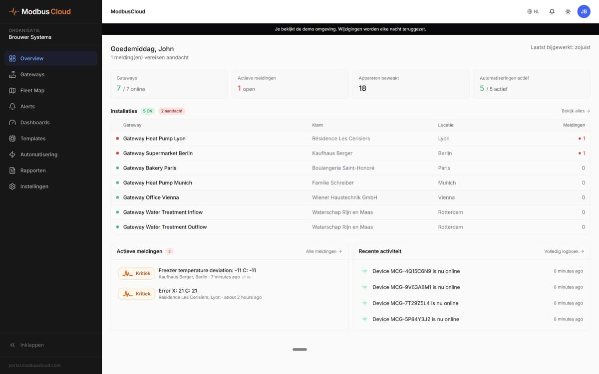
- Show the status and phase currents of every Emax 2 incomer and large feeder on one ModbusCloud dashboard.
- Send an email alert when a breaker trips or when a status word for alarms or warnings is no longer zero.
- Track active energy and power per feeder over 365 days of history to see where the load sits.
- Watch THD and harmonic ratios to spot non-linear loads before they overheat cables or transformers.
- Follow contact wear and the number of operations and trips to plan breaker maintenance.
Installation
Fit the Ekip Com Modbus RTU module in the Emax 2 terminal box and make sure the trip unit and module have auxiliary supply.
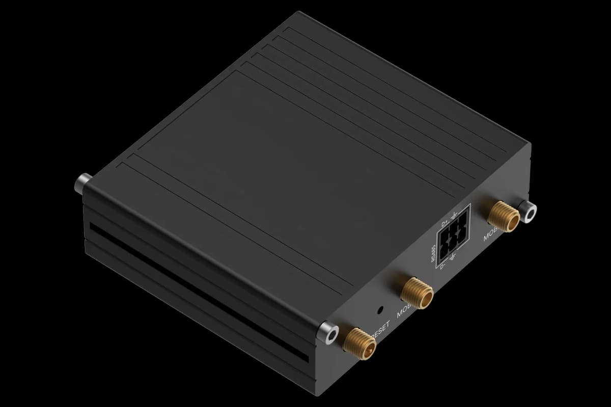
Wire the module's RS485 pair to RS485 A and B of the ModbusCloud Gateway with shielded twisted pair, and terminate the bus with 120 ohm at both ends.
Set the Modbus address, baud rate and parity on the Ekip Touch display; the default is address 247, 19200 baud, even parity.
In ModbusCloud, add a Modbus device on the Gateway with the same address and settings and import this template.
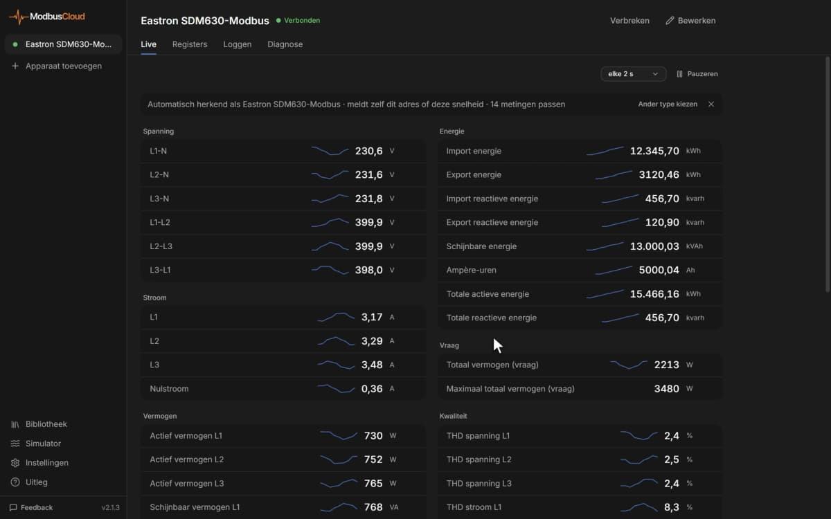
Check that breaker status, phase currents and frequency come in and match the trip unit display.
Things to watch for
The Ekip Com module does not answer. What should I check?
Check that the module has auxiliary supply and that address, baud rate and parity match the Gateway (default 247, 19200, even). Swap A and B if needed and terminate the bus at both ends. A racked-out breaker still answers, but then only the connection and position bits are valid.
Why are some measurements empty or not available?
Voltage, power and energy need the voltage measuring module (Measuring or Measurement Enabler). Without it those registers show the not available value. Legacy and Standard values are two formats of the same measurement, so you can use either.
Why do 32-bit values look wrong?
Ekip sends 32-bit values with the low word first, and this template reads them that way. If a value still looks wrong, check that you read the full two registers and not a single word.
Can I open, close or reset the breaker from ModbusCloud?
The command register accepts open, close, reset and trip reset commands, but only when the breaker is set to remote and the hardware allows it. Changing protection settings needs a programming session, so leave settings to the Ekip software. Test every write on site with the breaker in a safe state before you rely on it.




Want to see how it works?