

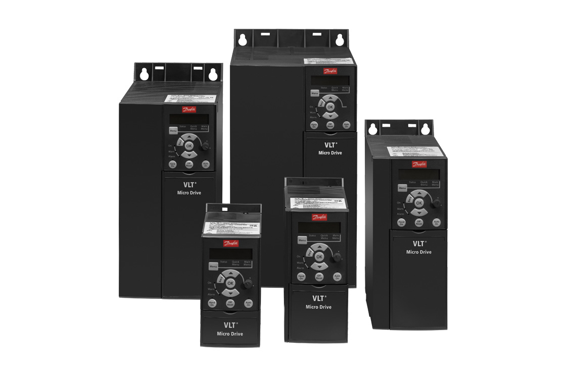
Danfoss VLT Micro Drive FC 51
Danfoss
Compact frequency converter: frequency, current, power, temperatures, alarm and warning words and hour counters over Modbus RTU.
Overview
Key readings
- Output frequency and motor current
- Output power in kW
- Motor voltage and DC link voltage
- Motor thermal and inverter thermal load
- Heat sink temperature
- Alarm word, warning word and status word
- Operating days, running hours and kWh counter
Use cases
- Get an alert when Alarm Word is not equal to 0, so you know a pump or fan drive tripped before the room gets too warm or too cold.
- Watch Heatsink Temperature and Inverter Thermal to find drives in hot cabinets that are close to derating.
- Log Power and Frequency to see how a fan follows its speed reference over the day.
- Track Running Hours and Operating Days to plan maintenance on the motor and the drive.
- Compare Motor Current with Inverter Nominal Current to check whether the drive size still fits the load.
Installation
- 1Connect terminal 68 (P) and 69 (N) of the drive to the RS485 port of your ModbusCloud Gateway, with 61 as common, and set switch BUS TER to ON on the last device of the line.
- 2On the drive set 8-30 Protocol to Modbus, check 8-31 Address (default 1), 8-32 Baud Rate (19200 with Modbus) and 8-33 Parity (even parity, 1 stop bit).
- 3In ModbusCloud, add a Modbus device (RTU) with address 1, 19200 baud, 8 data bits, even parity and 1 stop bit, then import this template.
- 4Check the link: DC Link Voltage should show a plausible value as soon as the drive has mains voltage, and Inverter Nominal Current should match the rating plate.
Things to watch for
- The drive does not answer after I switched to Modbus.
- After 8-30 Protocol = Modbus the drive uses 19200 baud by default instead of 9600 for the FC protocol, with even parity and 1 stop bit. Set the master the same way, check 8-31 Address and swap terminals 68 and 69 if nothing answers. BUS TER must be ON only at the ends of the line.
- Why does the alarm word show a large number?
- 16-90 Alarm Word, 16-92 Warning Word and 16-94 Extended Status Word are bit coded 32-bit values. The drive display shows them in hex. Convert the number to hex or binary and look up the bits in the alarm and warning list of the Operating Instructions. 0 means nothing is active.
- Frequency and current look 10 or 100 times too high.
- Danfoss transfers whole numbers with a conversion index: frequency has -1 (0.1 Hz), current -2 (0.01 A) and power -3 (0.001 kW). The template applies these factors. If you add your own parameters, take the conversion index from the parameter list.
- I get exception 02 when I read a parameter.
- The address is parameter number times ten minus one. 16-13 is PNU 1613, so the address is 16129. Reading 16130 or a parameter that does not exist on the FC 51 returns illegal data address. Text parameters in group 15-4x need multiple registers and are not in the template.
Registers (28)
28 read / 0 write
| Name | Address | Function | Type | Unit | Access |
|---|---|---|---|---|---|
Frequency Output frequency in 0.1 Hz (conversion index -1). Danfoss parameter 16-13 Frequency. | ••• | ••• | ••• | Hz | R |
Motor Current Motor current in 0.01 A (conversion index -2). Danfoss parameter 16-14 Motor Current. | ••• | ••• | ••• | A | R |
Power Output power, 0 to 99 kW, in 0.001 kW (conversion index -3). Danfoss parameter 16-10 Power [kW]. | ••• | ••• | ••• | kW | R |
Motor Voltage Motor voltage in V (conversion index 0). Danfoss parameter 16-12 Motor Voltage. | ••• | ••• | ••• | V | R |
Frequency Percent Output frequency in percent, 0.1 % (conversion index -1). Danfoss parameter 16-15 Frequency [%]. | ••• | ••• | ••• | % | R |
DC Link Voltage DC link voltage, 0 to 10000 V. Danfoss parameter 16-30 DC Link Voltage. | ••• | ••• | ••• | V | R |
Motor Thermal Calculated thermal motor load, 0 to 100 % of the estimated thermal load. Danfoss parameter 16-18 Motor Thermal (Uint8 in one register). | ••• | ••• | ••• | % | R |
Heatsink Temperature Heat sink temperature of the drive, 0 to 255 °C. Danfoss parameter 16-34 Heatsink Temp. (Uint8 in one register). | ••• | ••• | ••• | °C | R |
Inverter Thermal Calculated thermal load on the drive, 0 to 100 % of the estimated thermal load. Danfoss parameter 16-35 Inverter Thermal (Uint8 in one register). | ••• | ••• | ••• | % | R |
Status Word FC profile status word: bit 0 control ready, 1 drive ready, 2 not coasted, 3 tripped, 4 error without trip, 6 trip locked, 7 warning, 8 on reference, 9 auto mode, 10 in frequency range, 11 running, 13 voltage warning, 14 current limit, 15 thermal warning. Parameter 16-03. | ••• | ••• | ••• | R | |
Main Actual Value Main actual value sent with the status word, -100.00 to 100.00 % (conversion index -2). Danfoss parameter 16-05 Main Actual Value [%]. | ••• | ••• | ••• | % | R |
Alarm Word Alarm word, bit coded, 0 = no alarm. Shown as hex on the drive. Danfoss parameter 16-90 Alarm Word. | ••• | ••• | ••• | R | |
Warning Word Warning word, bit coded, 0 = no warning. Danfoss parameter 16-92 Warning Word. | ••• | ••• | ••• | R | |
Extended Status Word Extended status word, bit coded. Danfoss parameter 16-94 Ext. Status Word. | ••• | ••• | ••• | R | |
Feedback Process feedback in the unit configured in the drive, 0.001 resolution (conversion index -3). Danfoss parameter 16-52 Feedback [Unit]. | ••• | ••• | ••• | R | |
Analog Input 53 Voltage Analog input 53 in voltage mode, 0.01 V (conversion index -2). Danfoss parameter 16-62 Analog Input 53 (V). | ••• | ••• | ••• | V | R |
Analog Input 53 Current Analog input 53 in current mode, 0.01 mA (conversion index -2). Danfoss parameter 16-63 Analog Input 53 (mA). | ••• | ••• | ••• | mA | R |
Analog Input 60 Analog current input 60, 0.01 mA (conversion index -2). Danfoss parameter 16-64 Analog Input 60. | ••• | ••• | ••• | mA | R |
Analog Output 42 Analog output 42, 0.01 mA (conversion index -2). Danfoss parameter 16-65 Analog Output 42 [mA]. | ••• | ••• | ••• | mA | R |
Relay Output Relay setting, 0 or 1. Danfoss parameter 16-71 Relay Output [bin] (Uint8 in one register). | ••• | ••• | ••• | R | |
Inverter Nominal Current Nominal current of the drive in 0.01 A (conversion index -2). Danfoss parameter 16-36 Inv. Nom. Current. | ••• | ••• | ••• | A | R |
Inverter Max Current Intermittent maximum current of the drive (150 %) in 0.01 A. Danfoss parameter 16-37 Inv. Max. Current. | ••• | ••• | ••• | A | R |
Operating Days Days the drive has been powered up; saved at power off, cannot be reset. Danfoss parameter 15-00 Operating Time. | ••• | ••• | ••• | d | R |
Running Hours Running hours of the motor; can be reset with 15-07. Danfoss parameter 15-01 Running Hours. | ••• | ••• | ••• | h | R |
kWh Counter Danfoss parameter 15-02 kWh Counter, 0 to 65535; Danfoss describes it as power consumption in kWh as a mean value over one hour. Reset with 15-06. | ••• | ••• | ••• | kWh | R |
Power Ups Number of power-ups of the drive. Danfoss parameter 15-03 Power Ups. | ••• | ••• | ••• | R | |
Over Temperature Count Number of over-temperature events. Danfoss parameter 15-04 Over Temps. | ••• | ••• | ••• | R | |
Over Voltage Count Number of over-voltage events. Danfoss parameter 15-05 Over Volts. | ••• | ••• | ••• | R |
Loading registers…
Read the Danfoss VLT Micro Drive FC 51 remotely
We load the templates onto the gateway and set up your portal, you connect it at your customer's site. Tell us briefly what you need and we'll send a proposal.
From €295 + €149/year.
Prefer to configure it yourself? Order the gateway in the shop·Or see the live demo first
More Danfoss templates
More RTU templates

Alnor HRU
Alnor Systemy Wentylacji Sp. z o. o.
Controls and monitors Alnor heat recovery ventilation units via Modbus RTU.

connecdoor.controller
connecdoor
Controls and monitors smart door access points via RS485
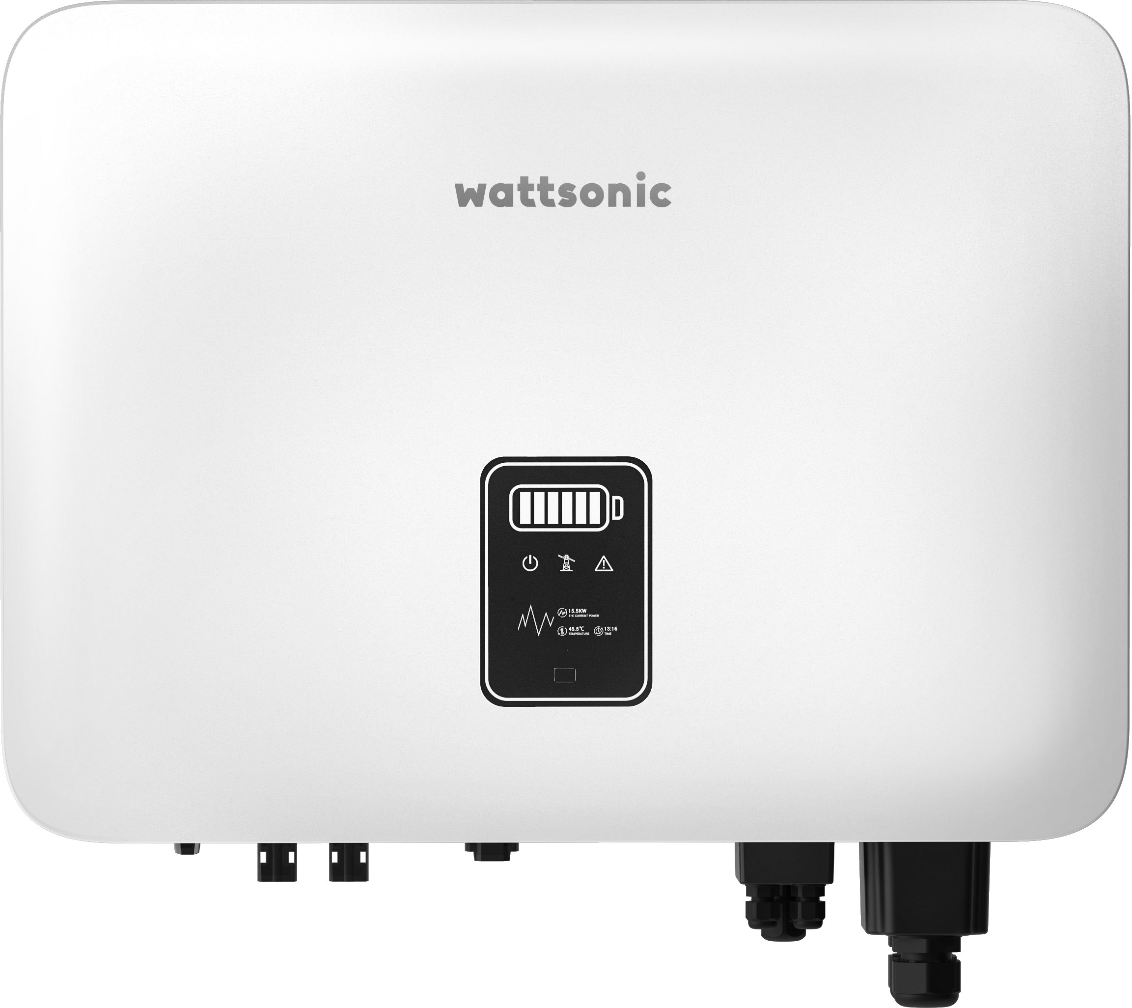
Wattsonic - Schmachtl Sun Energy Box
Wattsonic
Monitors Schmachtl Wattsonic hybrid inverter via Modbus RTU

Alnor HRU-P
Alnor Systemy Wentylacji Sp. z o. o.
Controls Alnor HRU-P heat recovery ventilation units via Modbus RTU.

Heidelberg Wallbox Energy Control
AMPERFIED GmbH
Controls and monitors Heidelberg Wallbox Energy Control EV charger via Modbus RTU.
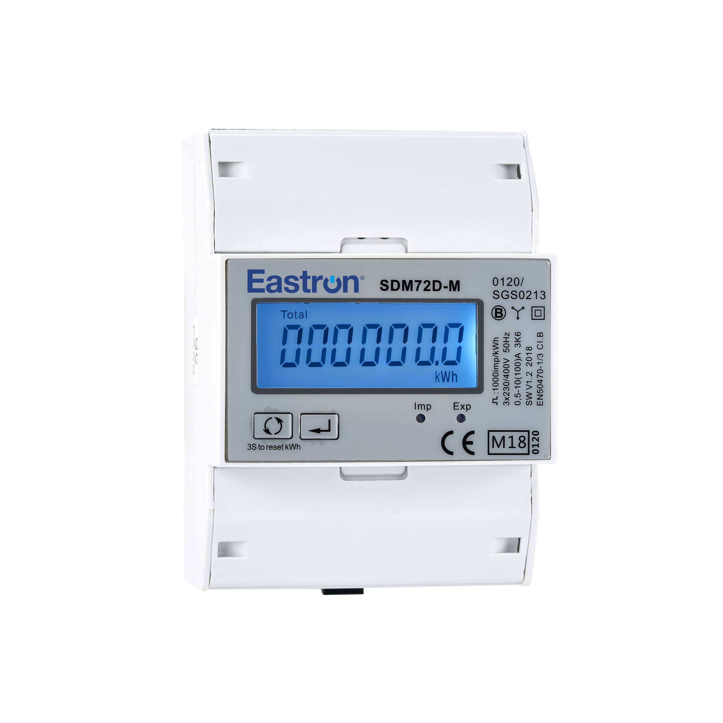
Eastron SDM72D-M
Eastron
Reads energy metering values from an Eastron SDM72D-M three-phase meter.