









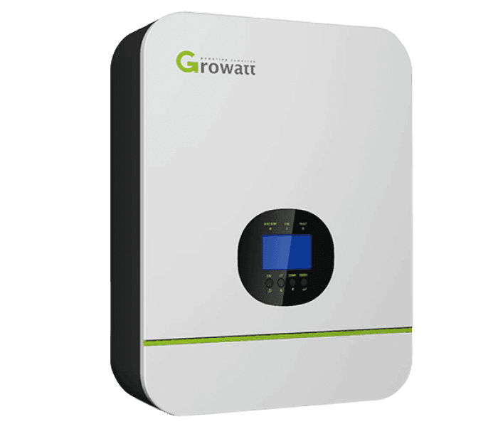
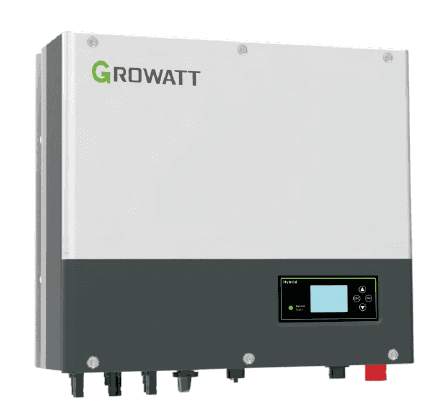
Growatt Hybrid Inverter (battery)
The Growatt Hybrid Inverter is a grid-tied hybrid PV inverter with integrated battery storage management, used in residential and small commercial solar-plus-storage systems. This Modbus RTU template reads battery power (power_a, power_b), battery state of charge, and cumulative energy throughput from the inverter over an RS485 connection. Two writable battery mode registers (batterymode_a, batterymode_b) allow remote switching between operating modes such as Grid First, Battery First, and Load First. The template gives installers and building owners live battery visibility and mode control from a single ModbusCloud Gateway.
- Protocol
- Modbus RTU
- Connection
- RS485
- Registers
- 6, read and write
- Brand
- Growatt
- Last updated
Registers (6)
4 read, 2 write
| Name | Unit | Access | Address (Hidden until you enter your email) | Function (hidden) | Type (hidden) |
|---|---|---|---|---|---|
| power_a | W | Read | |||
| power_b | W | Read | |||
| energy | Wh | Read | |||
| soc | % | Read | |||
| batterymode_a | Write | ||||
| batterymode_b | Write |
Loading registers…
Send your device list
If a device is not in the library yet, we build the template for free as soon as we have the register data.
Use cases
- Monitor battery state of charge continuously to detect gradual capacity fade across seasons.
- Track cumulative energy throughput to verify battery cycling against the manufacturer warranty threshold.
- Alert on unexpected drops in battery power to identify shading, BMS faults, or grid anomalies.
- Compare charge and discharge power trends to validate self-consumption improvements after tariff changes.
- Remotely switch battery operating mode via batterymode registers to align storage dispatch with dynamic energy prices.
Installation
Enable Modbus RTU communication on the Growatt Hybrid Inverter by navigating to the communication or advanced settings section of the inverter display and confirming the RS485 address and baud rate (9600, 8N1).
Connect the RS485 A and B terminals of the inverter to the RS485 port of the ModbusCloud Gateway using a twisted-pair cable; keep the cable run as short as possible and add a 120-ohm termination resistor at each end of the bus.
In the ModbusCloud portal, add the Gateway under your site, import the Growatt Hybrid Inverter (battery) template, and assign the correct Modbus unit ID matching the address set on the inverter.
Verify the connection by checking the live value of the soc register in the portal; a non-zero reading that matches the inverter display confirms the RS485 link is working correctly.
Things to watch for
Why do power_a and power_b always read zero?
Both registers are only populated when the battery is actively charging or discharging. If the inverter is in standby or the battery is at full charge with no load, both registers legitimately report zero. Confirm the battery is cycling and that the RS485 unit ID in the portal matches the address configured on the inverter display.
The Gateway connects but soc never updates. What is wrong?
The most common cause is a mismatch in baud rate or parity. The Growatt Hybrid Inverter uses 9600 bps, 8 data bits, no parity, and 1 stop bit. Verify these settings on the inverter and in the portal configuration. Also ensure the RS485 cable polarity (A+/B-) is not reversed between the inverter terminal and the Gateway.
I get intermittent timeouts on the RS485 bus. How do I fix this?
Growatt RTU firmware requires a minimum inter-command gap of 850 ms. If the Gateway polls too aggressively or shares the bus with another master, collisions cause timeouts. Set the poll interval to at least 1 second, add 120-ohm termination resistors at both ends of the cable run, and confirm no other device shares the same unit ID.
Is it safe to write to batterymode_a and batterymode_b remotely?
Use caution. Writing an unsupported mode value or switching modes during active charging can interrupt mid-cycle battery management and may affect system behaviour in ways not covered by warranty. Always test mode changes during low-load periods, confirm the intended mode is active on the inverter display afterward, and document each write in your maintenance log.
Want to see how it works?
