









Janitza UMG604
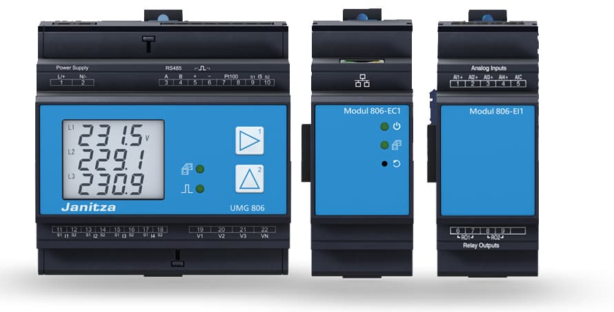
The Janitza UMG604 is a three-phase power quality analyser and energy meter used at main distribution points in commercial and industrial installations. This Modbus TCP template reads per-phase voltage, current, active power, and reactive power across all three phases, plus total active and reactive power, grid frequency, and cumulative consumption and production energy counters. Register values are IEEE 754 float32 and refresh every 200 ms. Connecting the UMG604 to ModbusCloud Gateway gives your portal continuous visibility into load balance, grid quality, and bidirectional energy flows without additional software.
- Protocol
- Modbus TCP
- Connection
- Ethernet, Modbus TCP
- Registers
- 17, read only
- Brand
- Janitza
- Last updated
Registers (17)
17 read, 0 write
| Name | Unit | Access | Address (Hidden until you enter your email) | Function (hidden) | Type (hidden) |
|---|---|---|---|---|---|
| voltage_l1 | V | Read | |||
| voltage_l2 | V | Read | |||
| voltage_l3 | V | Read | |||
| current_l1 | A | Read | |||
| current_l2 | A | Read | |||
| current_l3 | A | Read | |||
| active_power_l1 | W | Read | |||
| active_power_l2 | W | Read | |||
| active_power_l3 | W | Read | |||
| reactive_power_l1 | W | Read | |||
| reactive_power_l2 | W | Read | |||
| reactive_power_l3 | W | Read | |||
| active_power | W | Read | |||
| reactive_power | var | Read | |||
| frequency | Hz | Read | |||
| active_consumption_energy | Wh | Read | |||
| active_production_energy | Wh | Read |
Loading registers…
Send your device list
If a device is not in the library yet, we build the template for free as soon as we have the register data.
Use cases
- Monitor per-phase voltage and current to detect load imbalance across L1, L2, and L3 in real time.
- Track cumulative active consumption and production energy to verify monthly billing figures against utility invoices.
- Alert on total active power spikes to identify abnormal demand events before they trigger peak-tariff charges.
- Compare reactive power on each phase to assess power factor and determine whether capacitor correction is needed.
- Report grid frequency deviations over time to document power quality compliance for ISO 50001 audits.
Installation
Enable Modbus TCP on the UMG604 by entering programming mode (press both front buttons simultaneously for about one second) and assigning a static IP address, subnet mask, and unit ID under the communication or Modbus section.
Connect the UMG604 Ethernet port to the same LAN segment as the ModbusCloud Gateway using a standard patch cable; confirm the device responds to a ping from the gateway's network.
In your ModbusCloud portal, add a new device, select the Janitza UMG604 template, and enter the UMG604's IP address, TCP port 502, and the unit ID configured on the device (factory default is 1).
Verify the connection by checking live readings for voltage_l1 and active_power in the portal dashboard; values should update roughly every 200 ms and reflect actual site conditions.
Things to watch for
All register values show zero or NaN. What is wrong?
The UMG604 only produces valid measurements when at least one voltage input exceeds approximately 10 V RMS phase-to-neutral. Confirm the analyser is wired to live conductors and that current transformer connections are correct. Also verify the unit ID in the portal matches the value set on the device.
Float values look scrambled or wildly incorrect. Why?
Each float32 register spans two consecutive 16-bit Modbus words. If your master or gateway swaps word order, the decoded float will be garbage. The UMG604 uses big-endian (high word first) IEEE 754 encoding. Confirm your Modbus master is set to the same byte and word order before assuming a wiring fault.
The gateway connects but the portal shows no data. What should I check?
Confirm TCP port 502 is reachable from the gateway (not blocked by a local firewall or VLAN policy). The UMG604 can also act as a Modbus gateway to RS485 slave devices; if the unit ID is set to route to a downstream slave rather than the UMG604 itself, reads will fail. Set the unit ID to the value assigned to the UMG604 directly.
Address indexing appears off by one compared to the Janitza manual. Why?
Janitza's official Modbus address list uses zero-based addressing, while some Modbus masters add an offset of one. The addresses in this template follow the zero-based convention used by the OpenEMS implementation. If your readings are consistently shifted, check whether your master applies a +1 offset and adjust accordingly.



Want to see how it works?
