

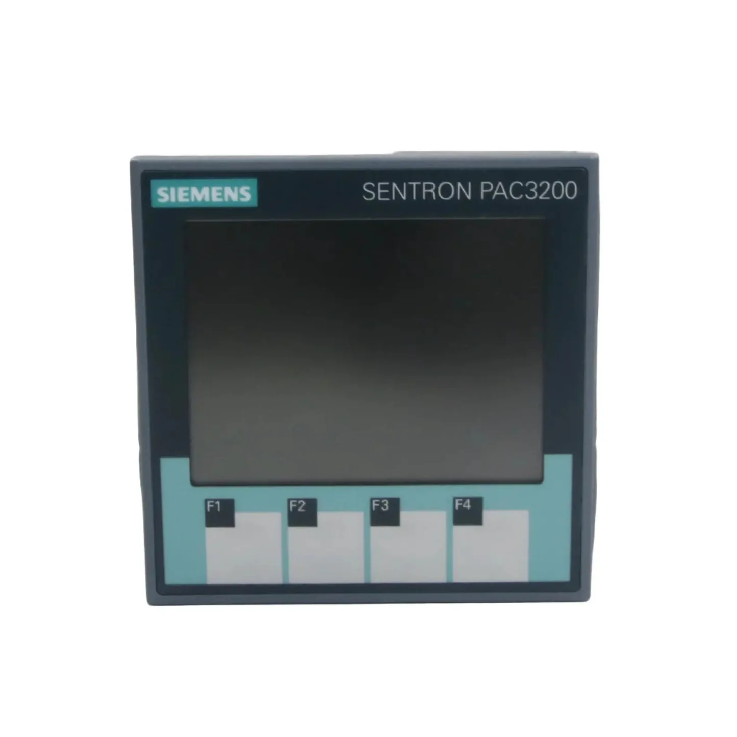
Siemens SENTRON PAC3200
Siemens
Three-phase power monitoring device: voltages, currents, power, power factor, THD, demand and status over Modbus RTU or TCP.
Overview
Key readings
- Phase-to-neutral and phase-to-phase voltages
- Current per phase and average current
- Active, reactive and apparent power per phase and in total
- Power factor per phase and total
- THD of voltage and current, voltage and current unbalance
- Frequency
- Demand values for import and export
- Device status, limit violations and operating hours
Use cases
- Alert when Total Active Power exceeds the contracted connection capacity of a building.
- Monitor Current L1, L2 and L3 and Current Unbalance to spot an overloaded phase in a distribution board.
- Track THD Voltage and THD Current per phase to find harmonic problems from drives or LED lighting.
- Compare Demand Active Power Import across weeks to plan peak shaving or a tariff change.
- Raise a warning when Device Status reports a voltage or current overload, or when Limit Violations is not 0.
- Log Total Power Factor to decide whether reactive power compensation is needed.
Installation
- 1Fit the PAC RS485 expansion module to the PAC3200 and connect its A and B terminals to the RS485 port of your ModbusCloud Gateway. Terminate both ends of the bus.
- 2On the meter, open SETTINGS > RS485 MODULE and check ADDRESS (default 126), BAUD RATE (19200), SETTINGS (8N2) and PROTOCOL (MODBUS RTU).
- 3For Modbus TCP instead, set IP ADDRESS, SUBNET and GATEWAY under SETTINGS > COMMUNICATION and switch PROTOCOL from SEAbus TCP to MODBUS TCP; the meter restarts.
- 4In ModbusCloud, add a Modbus device with the same address and serial settings (or the IP address and port 502), then import this template.
- 5Check the link: Frequency should read about 50 Hz and Voltage L1-N about 230 V on a standard low-voltage network.
Things to watch for
- The meter does not answer over RS485. What should I check?
- Modbus RTU only works with the PAC RS485 expansion module fitted. Check the module settings under SETTINGS > RS485 MODULE: default address 126, 19200 baud and 8N2, so two stop bits and no parity, which many tools do not use by default. Then swap A and B and check the termination at both ends of the bus.
- Modbus TCP connects but nothing comes back on port 502.
- The Ethernet port speaks SEAbus TCP by default. Switch PROTOCOL to MODBUS TCP under SETTINGS > COMMUNICATION and confirm the restart. Set IP address, subnet and gateway before the switch.
- Why do I get an exception or strange values when I read a register?
- Every measured value is a float in two registers. The PAC3200 returns an error when a read starts in the second register of a value, and a shifted address gives nonsense. Use the addresses exactly as in this template (Voltage L1-N at 1, Total Active Power at 65) with high word first.
- Where are the kWh counters?
- Siemens stores the energy counters (offset 801 onward) as 64-bit double values. ModbusCloud templates hold 16-bit and 32-bit values only, so they are not in this template. Demand Active Power Import and the power readings are included.
- Currents and power are far too low or too high.
- The PAC3200 applies the CT and VT ratios itself. Check Primary Current and Secondary Current, and with voltage transformers Primary Voltage and Secondary Voltage, against the installed transformers. Connection Type must match the wiring, for example 3P4W for a four-wire network.
- Several meters on one bus answer at random.
- Every device on the RS485 line needs its own address. All PAC RS485 modules leave the factory with address 126, so give each meter a unique address from 1 to 126 before you connect them together.
Registers (61)
61 read / 0 write
| Name | Address | Function | Type | Unit | Access |
|---|---|---|---|---|---|
Voltage L1-N Phase-to-neutral voltage L1-N in volts, IEEE 754 float. Manual name: Voltage Va-n. | ••• | ••• | ••• | V | R |
Voltage L2-N Phase-to-neutral voltage L2-N in volts, IEEE 754 float. Manual name: Voltage Vb-n. | ••• | ••• | ••• | V | R |
Voltage L3-N Phase-to-neutral voltage L3-N in volts, IEEE 754 float. Manual name: Voltage Vc-n. | ••• | ••• | ••• | V | R |
Voltage L1-L2 Phase-to-phase voltage L1-L2 in volts. Manual name: Voltage Va-b. | ••• | ••• | ••• | V | R |
Voltage L2-L3 Phase-to-phase voltage L2-L3 in volts. Manual name: Voltage Vb-c. | ••• | ••• | ••• | V | R |
Voltage L3-L1 Phase-to-phase voltage L3-L1 in volts. Manual name: Voltage Vc-a. | ••• | ••• | ••• | V | R |
Current L1 Current in phase L1 in amperes. Manual name: Current a. | ••• | ••• | ••• | A | R |
Current L2 Current in phase L2 in amperes. Manual name: Current b. | ••• | ••• | ••• | A | R |
Current L3 Current in phase L3 in amperes. Manual name: Current c. | ••• | ••• | ••• | A | R |
Active Power L1 Active power in phase L1 in watts. Manual name: Active Power a. | ••• | ••• | ••• | W | R |
Active Power L2 Active power in phase L2 in watts. Manual name: Active Power b. | ••• | ••• | ••• | W | R |
Active Power L3 Active power in phase L3 in watts. Manual name: Active Power c. | ••• | ••• | ••• | W | R |
Total Active Power Sum of the active power of all phases in watts. Manual name: Total Active Power. | ••• | ••• | ••• | W | R |
Total Reactive Power Sum of the reactive power of all phases in var. Manual name: Total Reactive Power. | ••• | ••• | ••• | var | R |
Total Apparent Power Sum of the apparent power of all phases in VA. Manual name: Total Apparent Power. | ••• | ••• | ••• | VA | R |
Total Power Factor Power factor over all phases. Manual name: Total Power Factor. | ••• | ••• | ••• | R | |
Frequency Mains frequency in hertz, range 45 to 65 Hz. Manual name: Frequency. | ••• | ••• | ••• | Hz | R |
Average Voltage L-N Average of the three phase-to-neutral voltages in volts. Manual name: Average Voltage Vph-n. | ••• | ••• | ••• | V | R |
Average Voltage L-L Average of the three phase-to-phase voltages in volts. Manual name: Average Voltage Vph-ph. | ••• | ••• | ••• | V | R |
Average Current Average of the three phase currents in amperes. Manual name: Average Current. | ••• | ••• | ••• | A | R |
Reactive Power L1 Reactive power in phase L1 in var. Manual name: Reactive Power a. | ••• | ••• | ••• | var | R |
Reactive Power L2 Reactive power in phase L2 in var. Manual name: Reactive Power b. | ••• | ••• | ••• | var | R |
Reactive Power L3 Reactive power in phase L3 in var. Manual name: Reactive Power c. | ••• | ••• | ••• | var | R |
Apparent Power L1 Apparent power in phase L1 in VA. Manual name: Apparent Power a. | ••• | ••• | ••• | VA | R |
Apparent Power L2 Apparent power in phase L2 in VA. Manual name: Apparent Power b. | ••• | ••• | ••• | VA | R |
Apparent Power L3 Apparent power in phase L3 in VA. Manual name: Apparent Power c. | ••• | ••• | ••• | VA | R |
Power Factor L1 Power factor of phase L1, range 0 to 1 per the manual. Manual name: Power Factor a. | ••• | ••• | ••• | R | |
Power Factor L2 Power factor of phase L2, range 0 to 1 per the manual. Manual name: Power Factor b. | ••• | ••• | ••• | R | |
Power Factor L3 Power factor of phase L3, range 0 to 1 per the manual. Manual name: Power Factor c. | ••• | ••• | ••• | R | |
THD Voltage L1 Total harmonic distortion (THD-R) of the voltage in phase L1, 0 to 100 %. Manual name: THD-R Voltage a. | ••• | ••• | ••• | % | R |
THD Voltage L2 Total harmonic distortion (THD-R) of the voltage in phase L2, 0 to 100 %. Manual name: THD-R Voltage b. | ••• | ••• | ••• | % | R |
THD Voltage L3 Total harmonic distortion (THD-R) of the voltage in phase L3, 0 to 100 %. Manual name: THD-R Voltage c. | ••• | ••• | ••• | % | R |
THD Current L1 Total harmonic distortion (THD-R) of the current in phase L1, 0 to 100 %. Manual name: THD-R Current a. | ••• | ••• | ••• | % | R |
THD Current L2 Total harmonic distortion (THD-R) of the current in phase L2, 0 to 100 %. Manual name: THD-R Current b. | ••• | ••• | ••• | % | R |
THD Current L3 Total harmonic distortion (THD-R) of the current in phase L3, 0 to 100 %. Manual name: THD-R Current c. | ••• | ••• | ••• | % | R |
Voltage Unbalance Amplitude unbalance of the voltage, 0 to 100 %. Manual name: Amplitude Unbalance - Voltage. | ••• | ••• | ••• | % | R |
Current Unbalance Amplitude unbalance of the current, 0 to 200 %. Manual name: Amplitude Unbalance - Current. | ••• | ••• | ••• | % | R |
Max Total Active Power Highest total active power since the maximum values were last reset, in watts. Manual name: Max. Total Active Power. | ••• | ••• | ••• | W | R |
Min Total Active Power Lowest total active power since the minimum values were last reset, in watts. Manual name: Min. Total Active Power. | ••• | ••• | ••• | W | R |
Demand Active Power Import Average active power drawn over the last completed demand period, in watts. Manual name: Demand Active Power - Import. | ••• | ••• | ••• | W | R |
Demand Reactive Power Import Average reactive power drawn over the last completed demand period, in var. Manual name: Demand Reactive Power - Import. | ••• | ••• | ••• | var | R |
Demand Active Power Export Average active power delivered over the last completed demand period, in watts. Manual name: Demand Active Power - Export. | ••• | ••• | ••• | W | R |
Demand Reactive Power Export Average reactive power delivered over the last completed demand period, in var. Manual name: Demand Reactive Power - Export. | ••• | ••• | ••• | var | R |
Max Active Power In Period Highest active power reading during the demand period, in watts. Manual name: Maximum Active Power Reading during the period. | ••• | ••• | ••• | W | R |
Demand Period Length Length of the demand period in seconds (set in minutes, 1 to 60, under Demand Period). Manual name: Demand Period. | ••• | ••• | ••• | s | R |
Time Since Demand Period Start Seconds elapsed since the start of the active demand period. Manual name: Time Since Start of the active demand period. | ••• | ••• | ••• | s | R |
Device Status Bitfield. 0x08000000 = current overload, 0x04000000 = voltage overload, 0x02000000 = configuration menu active, 0x01000000 = no sync pulse, 0x00000800 = device restarted, 0x00000200 = limit violation stored. 0 = no flag set. | ••• | ••• | ••• | R | |
Limit Violations Bitfield of the six programmable limits: 0x01 = limit 0 up to 0x20 = limit 5, 0x01000000 = limit logic. A set bit means the limit is violated. 0 = no violation. | ••• | ••• | ••• | R | |
Digital Input Status State of digital input 0 (bit mask 0x00000001). Manual name: Status of the digital inputs. | ••• | ••• | ••• | R | |
Digital Output Status State of digital output 0 (bit mask 0x00000001). Manual name: Status of the digital outputs. | ••• | ••• | ••• | R | |
Active Tariff Tariff that the energy counters are currently counting in: 0 = tariff 1, 1 = tariff 2. Manual name: Active Tariff. | ••• | ••• | ••• | R | |
Working Hours Counter Operating time counter in seconds, 0 to 999999999. Read only in this template although the manual allows writing it. Manual name: Working hours counter. | ••• | ••• | ••• | s | R |
Universal Counter Counts pulses or events from the source set under Universal counter source (digital input, digital output or a limit), 0 to 999999999. | ••• | ••• | ••• | R | |
Relevant Parameter Changes Number of changes to parameters that affect the measurement. Manual name: Relevant Parameter Changes Counter. | ••• | ••• | ••• | R | |
All Parameter Changes Number of changes to any device parameter. Manual name: Counter All Parameter Changes. | ••• | ••• | ••• | R | |
Connection Type Configured wiring: 0 = 3P4W, 1 = 3P3W, 2 = 3P4WB, 3 = 3P3WB, 4 = 1P2W. Read only in this template. Manual name: Connection type. | ••• | ••• | ••• | R | |
Primary Current Configured CT primary current, 1 to 99999 A. Read only in this template. Manual name: Primary current. | ••• | ••• | ••• | A | R |
Secondary Current Configured CT secondary current, 1 A or 5 A. Read only in this template. Manual name: Secondary current. | ••• | ••• | ••• | A | R |
Primary Voltage Configured VT primary voltage, 1 to 999999 V, only used when voltage transformers are enabled. Read only in this template. | ••• | ••• | ••• | V | R |
Secondary Voltage Configured VT secondary voltage, 1 to 690 V, only used when voltage transformers are enabled. Read only in this template. | ••• | ••• | ••• | V | R |
Demand Period Setting Configured demand period in minutes, 1 to 60. Read only in this template. Manual name: Demand Period. | ••• | ••• | ••• | min | R |
Loading registers…
Read the Siemens SENTRON PAC3200 remotely
We load the templates onto the gateway and set up your portal, you connect it at your customer's site. Tell us briefly what you need and we'll send a proposal.
From €295 + €149/year.
Prefer to configure it yourself? Order the gateway in the shop·Or see the live demo first
More Siemens templates

Siemens Junelight Smart Battery (battery)
Siemens
Siemens Sentron PAC3100 Power meter 3 phase
Siemens
Reads 3-phase power metering data from a Siemens Sentron PAC3100.
Siemens 7KT1665 (grid)
Siemens
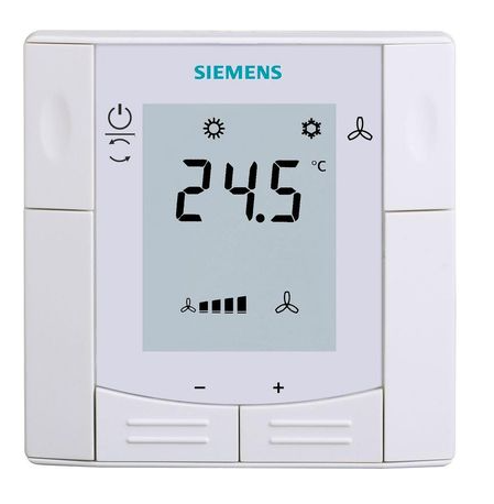
Siemens RDF660MB
Siemens
Controls a Siemens room thermostat via Modbus RTU
Siemens Sentron PAC 2200
Siemens
Monitors three-phase energy metering via Modbus TCP on Siemens Sentron PAC 2200.

Siemens RDF302
Siemens
Controls a Siemens room thermostat via Modbus RTU
More RTU templates

Alnor HRU
Alnor Systemy Wentylacji Sp. z o. o.
Controls and monitors Alnor heat recovery ventilation units via Modbus RTU.

connecdoor.controller
connecdoor
Controls and monitors smart door access points via RS485
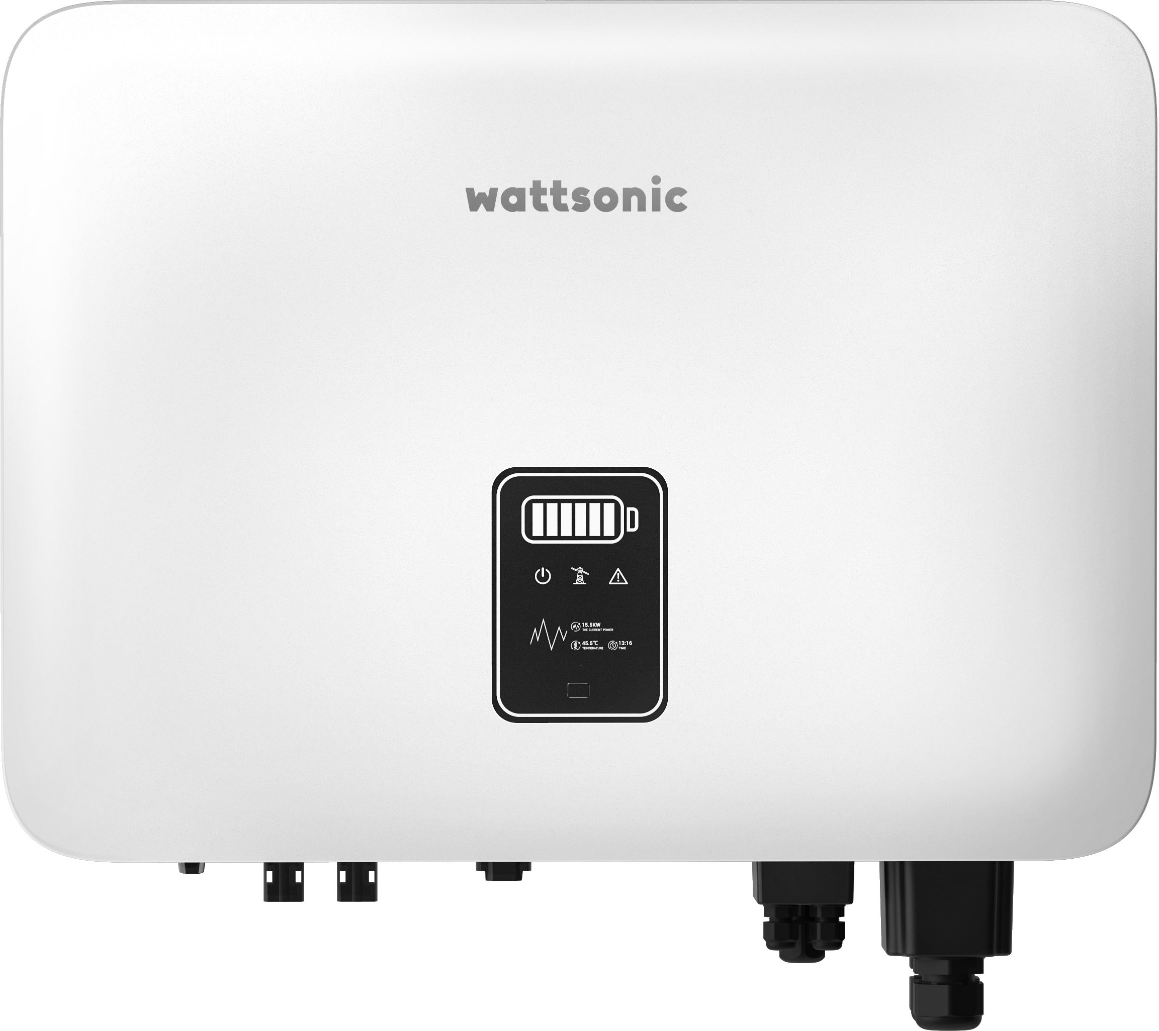
Wattsonic - Schmachtl Sun Energy Box
Wattsonic
Monitors Schmachtl Wattsonic hybrid inverter via Modbus RTU

Alnor HRU-P
Alnor Systemy Wentylacji Sp. z o. o.
Controls Alnor HRU-P heat recovery ventilation units via Modbus RTU.

Heidelberg Wallbox Energy Control
AMPERFIED GmbH
Controls and monitors Heidelberg Wallbox Energy Control EV charger via Modbus RTU.
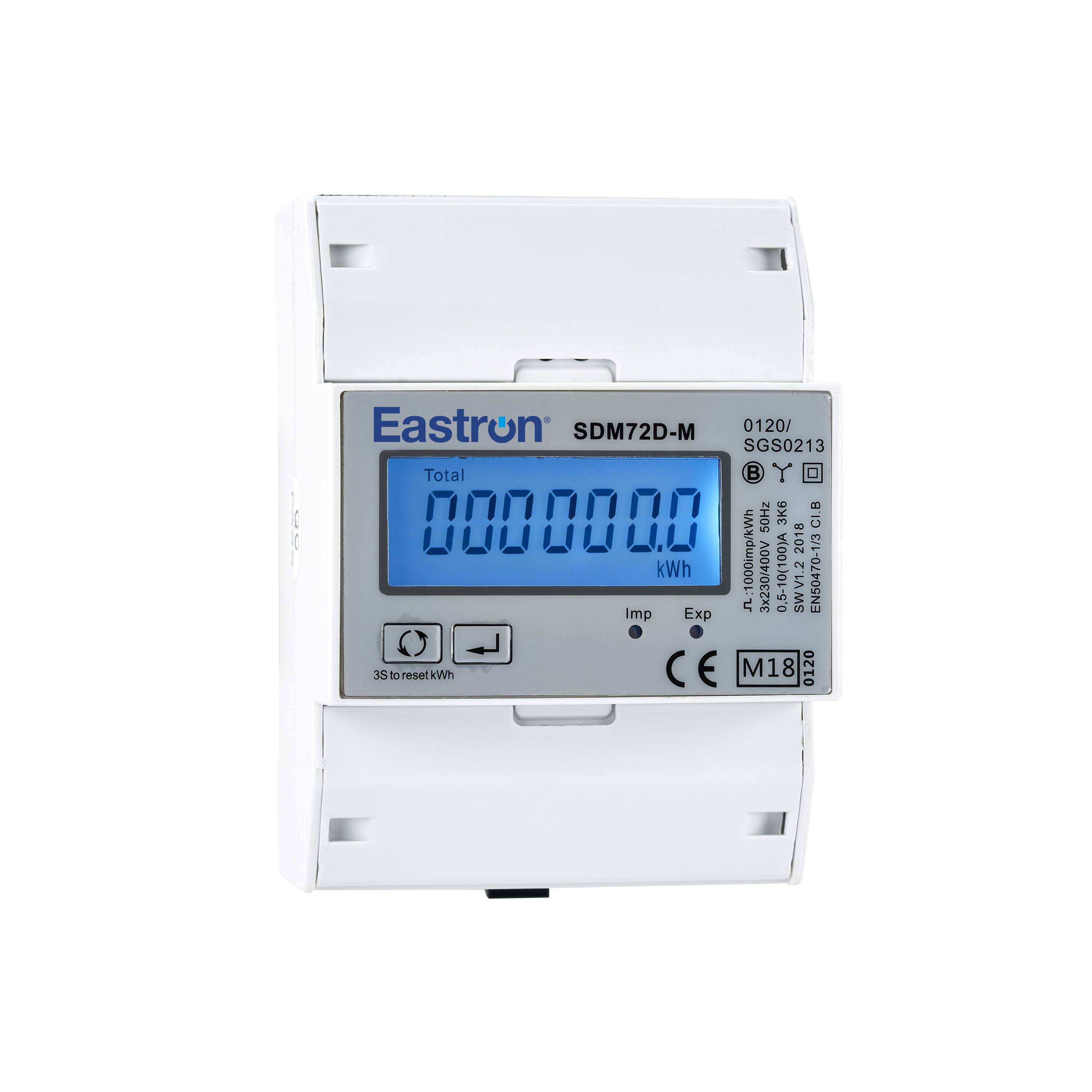
Eastron SDM72D-M
Eastron
Reads energy metering values from an Eastron SDM72D-M three-phase meter.