

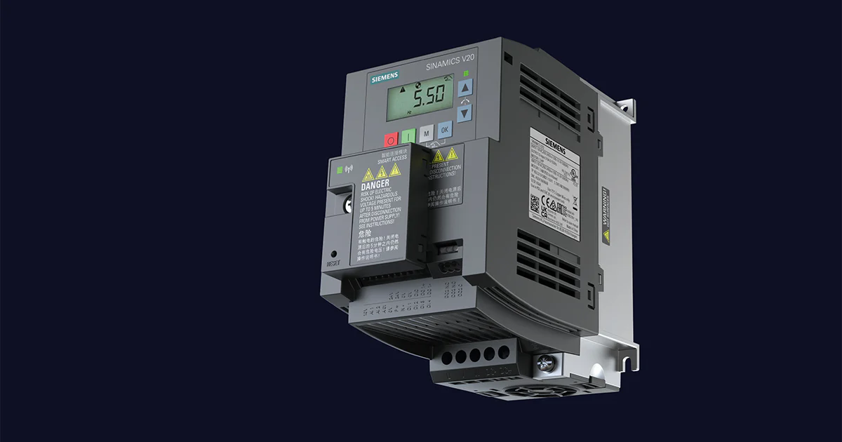
Siemens SINAMICS V20
Siemens
Compact frequency converter: frequency, current, power, faults and remote start, stop and setpoint.
Overview
Key readings
- Output frequency
- Motor speed
- Output current
- Actual power
- Energy consumption
- Last fault
- DC bus voltage
Available commands
- Start and stop
- Frequency setpoint
- Direction
- Ramp times
- Fixed frequencies
- PID setpoint
Use cases
- Show frequency, current and power of every pump and fan drive on one dashboard.
- Get an email when the fault bit is set or the output current rises above a threshold you set.
- Track energy consumption per drive in the history to compare motors and running hours.
- Lower the frequency setpoint of a fan at night with an automation on a schedule.
- Adjust ramp times, fixed frequencies or the PID setpoint remotely after commissioning.
Installation
- 1Wire the RS485 terminals P+ and N- of the converter to the RS485 A and B terminals of the ModbusCloud Gateway and terminate the bus at both ends.
- 2On the converter, set P0003 = 3, P2023 = 2 (Modbus) and P0700 = 5 for control over RS485; check P2021 (address 1) and P2010 (9600 baud).
- 3Switch the converter off, wait until the display is blank, and switch it on again so the protocol change takes effect.
- 4In ModbusCloud, add a Modbus device (RTU) with address 1, 9600 baud, 8 data bits, even parity and 1 stop bit, and import this template.
- 5Check that DC bus voltage and converter version show plausible values.
Things to watch for
- The converter does not answer. What should I check?
- Check P2023 = 2 and power-cycle the converter after changing it; wait until the display is blank before switching on. Check address P2021, baud rate P2010, parity P2034 and stop bits P2035 against the device in ModbusCloud. Swap P+ and N- if nothing comes back.
- Why does the converter trip with fault F72?
- When the controller sends process data, the converter monitors the time between telegrams with P2014. If no new telegram arrives in time, it trips with F72. Increase P2014 or set it to 0 when the converter is only monitored.
- Can several converters share one RS485 line?
- Yes. Give each converter its own address in P2021 (1 to 247) and use the same baud rate and parity on all of them. Wire the bus as one line from converter to converter and terminate both ends.
- What should I keep in mind when I write settings?
- Start, stop and setpoint only work when P0700 = 5. Writes take effect immediately. Writing a digital output sets its interconnection to a fixed 0 or 1 and the previous link is lost. Read the current value first and change one setting at a time.
Registers (262)
262 read / 186 write
| Name | Address | Function | Type | Unit | Access |
|---|---|---|---|---|---|
| Watchdog Time | ••• | ••• | ••• | ms | R/W |
| Watchdog Action | ••• | ••• | ••• | R/W | |
| Frequency Setpoint | ••• | ••• | ••• | % | R/W |
| Run Enable | ••• | ••• | ••• | R/W | |
| Forward/Reverse Command | ••• | ••• | ••• | R/W | |
| Start Command | ••• | ••• | ••• | R/W | |
| Fault Acknowledgement | ••• | ••• | ••• | R/W | |
| PID Setpoint Reference | ••• | ••• | ••• | % | R/W |
| PID Enable | ••• | ••• | ••• | R/W | |
| Current Limit | ••• | ••• | ••• | % | R/W |
| Acceleration Time | ••• | ••• | ••• | s | R/W |
| Deceleration Time | ••• | ••• | ••• | s | R/W |
| Digital Output 1 | ••• | ••• | ••• | R/W | |
| Digital Output 2 | ••• | ••• | ••• | R/W | |
| Reference Frequency | ••• | ••• | ••• | Hz | R/W |
| PID Upper Limit | ••• | ••• | ••• | % | R/W |
| PID Lower Limit | ••• | ••• | ••• | % | R/W |
| Proportional Gain | ••• | ••• | ••• | R/W | |
| Integral Gain | ••• | ••• | ••• | s | R/W |
| Differential Gain | ••• | ••• | ••• | R/W | |
| Feedback Gain | ••• | ••• | ••• | % | R/W |
| Low Pass | ••• | ••• | ••• | R/W | |
| Frequency Output | ••• | ••• | ••• | Hz | R |
| Speed | ••• | ••• | ••• | rpm | R |
| Current Filtered | ••• | ••• | ••• | A | R |
| Torque | ••• | ••• | ••• | Nm | R |
| Actual Power | ••• | ••• | ••• | kW | R |
| Total kWh | ••• | ••• | ••• | kWh | R |
| DC Bus Voltage | ••• | ••• | ••• | V | R |
| Reference | ••• | ••• | ••• | Hz | R |
| Rated Power | ••• | ••• | ••• | kW | R |
| Voltage Output | ••• | ••• | ••• | V | R |
| Forward/Reverse | ••• | ••• | ••• | R | |
| Stop/Run | ••• | ••• | ••• | R | |
| Run At Maximum Frequency | ••• | ••• | ••• | R | |
| Control Mode | ••• | ••• | ••• | R | |
| Enabled | ••• | ••• | ••• | R | |
| Ready To Run | ••• | ••• | ••• | R | |
| Analog Input 1 | ••• | ••• | ••• | % | R |
| Analog Input 2 | ••• | ••• | ••• | % | R |
| Analog Output 1 | ••• | ••• | ••• | % | R |
| Actual Frequency | ••• | ••• | ••• | % | R |
| PID Setpoint Output | ••• | ••• | ••• | % | R |
| PID Output | ••• | ••• | ••• | % | R |
| PID Feedback | ••• | ••• | ••• | % | R |
| Digital Input 1 | ••• | ••• | ••• | R | |
| Digital Input 2 | ••• | ••• | ••• | R | |
| Digital Input 3 | ••• | ••• | ••• | R | |
| Digital Input 4 | ••• | ••• | ••• | R | |
| Fault | ••• | ••• | ••• | R | |
| Last Fault | ••• | ••• | ••• | R | |
| Fault 1 | ••• | ••• | ••• | R | |
| Fault 2 | ••• | ••• | ••• | R | |
| Fault 3 | ••• | ••• | ••• | R | |
| Warning | ••• | ••• | ••• | R | |
| Last Warning | ••• | ••• | ••• | R | |
| Converter Version | ••• | ••• | ••• | R | |
| Converter Model | ••• | ••• | ••• | R | |
| Control Word | ••• | ••• | ••• | R/W | |
| Main Setpoint | ••• | ••• | ••• | R/W | |
| Status Word | ••• | ••• | ••• | R | |
| Main Actual Value | ••• | ••• | ••• | R | |
| Digital Output 1 (Reg 40200) | ••• | ••• | ••• | R/W | |
| Digital Output 2 (Reg 40201) | ••• | ••• | ••• | R/W | |
| Digital Output 3 | ••• | ••• | ••• | R/W | |
| Digital Output 4 | ••• | ••• | ••• | R/W | |
| Analog Output 1 (Reg 40220) | ••• | ••• | ••• | % | R |
| Digital Input 1 (Reg 40240) | ••• | ••• | ••• | R | |
| Digital Input 2 (Reg 40241) | ••• | ••• | ••• | R | |
| Digital Input 3 (Reg 40242) | ••• | ••• | ••• | R | |
| Digital Input 4 (Reg 40243) | ••• | ••• | ••• | R | |
| Digital Input 5 | ••• | ••• | ••• | R | |
| Digital Input 6 | ••• | ••• | ••• | R | |
| Analog Input 1 (Reg 40260) | ••• | ••• | ••• | % | R |
| Analog Input 2 (Reg 40261) | ••• | ••• | ••• | % | R |
| Converter Model (Reg 40300) | ••• | ••• | ••• | R | |
| Converter Version (Reg 40301) | ••• | ••• | ••• | R | |
| Rated Power (Reg 40320) | ••• | ••• | ••• | kW | R |
| Current Limit (Reg 40321) | ••• | ••• | ••• | % | R/W |
| Acceleration Time (Reg 40322) | ••• | ••• | ••• | s | R/W |
| Deceleration Time (Reg 40323) | ••• | ••• | ••• | s | R/W |
| Reference Frequency (Reg 40324) | ••• | ••• | ••• | Hz | R/W |
| Fixed Frequency 1 | ••• | ••• | ••• | Hz | R/W |
| Fixed Frequency 2 | ••• | ••• | ••• | Hz | R/W |
| Fixed Frequency 3 | ••• | ••• | ••• | Hz | R/W |
| Fixed Frequency 4 | ••• | ••• | ••• | Hz | R/W |
| Fixed Setpoint 1 | ••• | ••• | ••• | % | R/W |
| Fixed Setpoint 2 | ••• | ••• | ••• | % | R/W |
| Fixed Frequency 5 | ••• | ••• | ••• | Hz | R/W |
| Fixed Frequency 6 | ••• | ••• | ••• | Hz | R/W |
| Fixed Frequency 7 | ••• | ••• | ••• | Hz | R/W |
| Fixed Frequency 8 | ••• | ••• | ••• | Hz | R/W |
| Reference (Reg 40340) | ••• | ••• | ••• | Hz | R |
| Speed (Reg 40341) | ••• | ••• | ••• | rpm | R |
| Frequency Output (Reg 40342) | ••• | ••• | ••• | Hz | R |
| Voltage Output (Reg 40343) | ••• | ••• | ••• | V | R |
| DC Bus Voltage (Reg 40344) | ••• | ••• | ••• | V | R |
| Current Filtered (Reg 40345) | ••• | ••• | ••• | A | R |
| Torque (Reg 40346) | ••• | ••• | ••• | Nm | R |
| Actual Power (Reg 40347) | ••• | ••• | ••• | kW | R |
| Total kWh (Reg 40348) | ••• | ••• | ••• | kWh | R |
| Hand/Auto | ••• | ••• | ••• | R | |
| Current Unfiltered | ••• | ••• | ••• | A | R |
| Continuous Boost | ••• | ••• | ••• | % | R/W |
| Minimum Frequency | ••• | ••• | ••• | Hz | R/W |
| Maximum Frequency | ••• | ••• | ••• | Hz | R/W |
| JOG Frequency Index 0 | ••• | ••• | ••• | Hz | R/W |
| JOG Frequency Index 1 | ••• | ••• | ••• | Hz | R/W |
| JOG Frequency Index 2 | ••• | ••• | ••• | Hz | R/W |
| JOG Frequency Left Index 0 | ••• | ••• | ••• | Hz | R/W |
| JOG Frequency Left Index 1 | ••• | ••• | ••• | Hz | R/W |
| JOG Frequency Left Index 2 | ••• | ••• | ••• | Hz | R/W |
| Fault 1 (Reg 40400) | ••• | ••• | ••• | R | |
| Fault 2 (Reg 40401) | ••• | ••• | ••• | R | |
| Fault 3 (Reg 40402) | ••• | ••• | ••• | R | |
| Fault 4 | ••• | ••• | ••• | R | |
| Fault 5 | ••• | ••• | ••• | R | |
| Fault 6 | ••• | ••• | ••• | R | |
| Fault 7 | ••• | ••• | ••• | R | |
| Fault 8 | ••• | ••• | ••• | R | |
| Warning (Reg 40408) | ••• | ••• | ••• | R | |
| Parameter Error Code | ••• | ••• | ••• | R | |
| PID Enable (Reg 40500) | ••• | ••• | ••• | R/W | |
| PID Setpoint Reference (Reg 40501) | ••• | ••• | ••• | % | R/W |
| Low Pass (Reg 40510) | ••• | ••• | ••• | R/W | |
| Feedback Gain (Reg 40511) | ••• | ••• | ••• | % | R/W |
| Proportional Gain (Reg 40512) | ••• | ••• | ••• | R/W | |
| Integral Gain (Reg 40513) | ••• | ••• | ••• | s | R/W |
| Differential Gain (Reg 40514) | ••• | ••• | ••• | R/W | |
| PID Upper Limit (Reg 40515) | ••• | ••• | ••• | % | R/W |
| PID Lower Limit (Reg 40516) | ••• | ••• | ••• | % | R/W |
| PID Setpoint Output (Reg 40520) | ••• | ••• | ••• | % | R |
| PID Feedback (Reg 40521) | ••• | ••• | ••• | % | R |
| PID Output (Reg 40522) | ••• | ••• | ••• | % | R |
| Parameter Number | ••• | ••• | ••• | R/W | |
| Parameter Index | ••• | ••• | ••• | R/W | |
| Parameter Upper Word | ••• | ••• | ••• | R/W | |
| Parameter Lower Word | ••• | ••• | ••• | R/W | |
| Parameter Upper Word (Reg 40558) | ••• | ••• | ••• | R | |
| Parameter Lower Word (Reg 40559) | ••• | ••• | ••• | R | |
| DS47 Control | ••• | ••• | ••• | R/W | |
| DS47 Header | ••• | ••• | ••• | R/W | |
| DS47 Data 1 | ••• | ••• | ••• | R/W | |
| DS47 Data 2 | ••• | ••• | ••• | R/W | |
| DS47 Data 3 | ••• | ••• | ••• | R/W | |
| DS47 Data 4 | ••• | ••• | ••• | R/W | |
| DS47 Data 5 | ••• | ••• | ••• | R/W | |
| DS47 Data 6 | ••• | ••• | ••• | R/W | |
| DS47 Data 7 | ••• | ••• | ••• | R/W | |
| DS47 Data 8 | ••• | ••• | ••• | R/W | |
| DS47 Data 9 | ••• | ••• | ••• | R/W | |
| DS47 Data 10 | ••• | ••• | ••• | R/W | |
| DS47 Data 11 | ••• | ••• | ••• | R/W | |
| DS47 Data 12 | ••• | ••• | ••• | R/W | |
| DS47 Data 13 | ••• | ••• | ••• | R/W | |
| DS47 Data 14 | ••• | ••• | ••• | R/W | |
| DS47 Data 15 | ••• | ••• | ••• | R/W | |
| DS47 Data 16 | ••• | ••• | ••• | R/W | |
| DS47 Data 17 | ••• | ••• | ••• | R/W | |
| DS47 Data 18 | ••• | ••• | ••• | R/W | |
| DS47 Data 19 | ••• | ••• | ••• | R/W | |
| DS47 Data 20 | ••• | ••• | ••• | R/W | |
| DS47 Data 21 | ••• | ••• | ••• | R/W | |
| DS47 Data 22 | ••• | ••• | ••• | R/W | |
| DS47 Data 23 | ••• | ••• | ••• | R/W | |
| DS47 Data 24 | ••• | ••• | ••• | R/W | |
| DS47 Data 25 | ••• | ••• | ••• | R/W | |
| DS47 Data 26 | ••• | ••• | ••• | R/W | |
| DS47 Data 27 | ••• | ••• | ••• | R/W | |
| DS47 Data 28 | ••• | ••• | ••• | R/W | |
| DS47 Data 29 | ••• | ••• | ••• | R/W | |
| DS47 Data 30 | ••• | ••• | ••• | R/W | |
| DS47 Data 31 | ••• | ••• | ••• | R/W | |
| DS47 Data 32 | ••• | ••• | ••• | R/W | |
| DS47 Data 33 | ••• | ••• | ••• | R/W | |
| DS47 Data 34 | ••• | ••• | ••• | R/W | |
| DS47 Data 35 | ••• | ••• | ••• | R/W | |
| DS47 Data 36 | ••• | ••• | ••• | R/W | |
| DS47 Data 37 | ••• | ••• | ••• | R/W | |
| DS47 Data 38 | ••• | ••• | ••• | R/W | |
| DS47 Data 39 | ••• | ••• | ••• | R/W | |
| DS47 Data 40 | ••• | ••• | ••• | R/W | |
| DS47 Data 41 | ••• | ••• | ••• | R/W | |
| DS47 Data 42 | ••• | ••• | ••• | R/W | |
| DS47 Data 43 | ••• | ••• | ••• | R/W | |
| DS47 Data 44 | ••• | ••• | ••• | R/W | |
| DS47 Data 45 | ••• | ••• | ••• | R/W | |
| DS47 Data 46 | ••• | ••• | ••• | R/W | |
| DS47 Data 47 | ••• | ••• | ••• | R/W | |
| DS47 Data 48 | ••• | ••• | ••• | R/W | |
| DS47 Data 49 | ••• | ••• | ••• | R/W | |
| DS47 Data 50 | ••• | ••• | ••• | R/W | |
| DS47 Data 51 | ••• | ••• | ••• | R/W | |
| DS47 Data 52 | ••• | ••• | ••• | R/W | |
| DS47 Data 53 | ••• | ••• | ••• | R/W | |
| DS47 Data 54 | ••• | ••• | ••• | R/W | |
| DS47 Data 55 | ••• | ••• | ••• | R/W | |
| DS47 Data 56 | ••• | ••• | ••• | R/W | |
| DS47 Data 57 | ••• | ••• | ••• | R/W | |
| DS47 Data 58 | ••• | ••• | ••• | R/W | |
| DS47 Data 59 | ••• | ••• | ••• | R/W | |
| DS47 Data 60 | ••• | ••• | ••• | R/W | |
| DS47 Data 61 | ••• | ••• | ••• | R/W | |
| DS47 Data 62 | ••• | ••• | ••• | R/W | |
| DS47 Data 63 | ••• | ••• | ••• | R/W | |
| DS47 Data 64 | ••• | ••• | ••• | R/W | |
| DS47 Data 65 | ••• | ••• | ••• | R/W | |
| DS47 Data 66 | ••• | ••• | ••• | R/W | |
| DS47 Data 67 | ••• | ••• | ••• | R/W | |
| DS47 Data 68 | ••• | ••• | ••• | R/W | |
| DS47 Data 69 | ••• | ••• | ••• | R/W | |
| DS47 Data 70 | ••• | ••• | ••• | R/W | |
| DS47 Data 71 | ••• | ••• | ••• | R/W | |
| DS47 Data 72 | ••• | ••• | ••• | R/W | |
| DS47 Data 73 | ••• | ••• | ••• | R/W | |
| DS47 Data 74 | ••• | ••• | ••• | R/W | |
| DS47 Data 75 | ••• | ••• | ••• | R/W | |
| DS47 Data 76 | ••• | ••• | ••• | R/W | |
| DS47 Data 77 | ••• | ••• | ••• | R/W | |
| DS47 Data 78 | ••• | ••• | ••• | R/W | |
| DS47 Data 79 | ••• | ••• | ••• | R/W | |
| DS47 Data 80 | ••• | ••• | ••• | R/W | |
| DS47 Data 81 | ••• | ••• | ••• | R/W | |
| DS47 Data 82 | ••• | ••• | ••• | R/W | |
| DS47 Data 83 | ••• | ••• | ••• | R/W | |
| DS47 Data 84 | ••• | ••• | ••• | R/W | |
| DS47 Data 85 | ••• | ••• | ••• | R/W | |
| DS47 Data 86 | ••• | ••• | ••• | R/W | |
| DS47 Data 87 | ••• | ••• | ••• | R/W | |
| DS47 Data 88 | ••• | ••• | ••• | R/W | |
| DS47 Data 89 | ••• | ••• | ••• | R/W | |
| DS47 Data 90 | ••• | ••• | ••• | R/W | |
| DS47 Data 91 | ••• | ••• | ••• | R/W | |
| DS47 Data 92 | ••• | ••• | ••• | R/W | |
| DS47 Data 93 | ••• | ••• | ••• | R/W | |
| DS47 Data 94 | ••• | ••• | ••• | R/W | |
| DS47 Data 95 | ••• | ••• | ••• | R/W | |
| DS47 Data 96 | ••• | ••• | ••• | R/W | |
| DS47 Data 97 | ••• | ••• | ••• | R/W | |
| DS47 Data 98 | ••• | ••• | ••• | R/W | |
| DS47 Data 99 | ••• | ••• | ••• | R/W | |
| DS47 Data 100 | ••• | ••• | ••• | R/W | |
| DS47 Data 101 | ••• | ••• | ••• | R/W | |
| DS47 Data 102 | ••• | ••• | ••• | R/W | |
| DS47 Data 103 | ••• | ••• | ••• | R/W | |
| DS47 Data 104 | ••• | ••• | ••• | R/W | |
| DS47 Data 105 | ••• | ••• | ••• | R/W | |
| DS47 Data 106 | ••• | ••• | ••• | R/W | |
| DS47 Data 107 | ••• | ••• | ••• | R/W | |
| DS47 Data 108 | ••• | ••• | ••• | R/W | |
| DS47 Data 109 | ••• | ••• | ••• | R/W | |
| DS47 Data 110 | ••• | ••• | ••• | R/W | |
| DS47 Data 111 | ••• | ••• | ••• | R/W | |
| DS47 Data 112 | ••• | ••• | ••• | R/W | |
| DS47 Data 113 | ••• | ••• | ••• | R/W | |
| DS47 Data 114 | ••• | ••• | ••• | R/W | |
| DS47 Data 115 | ••• | ••• | ••• | R/W | |
| DS47 Data 116 | ••• | ••• | ••• | R/W | |
| DS47 Data 117 | ••• | ••• | ••• | R/W | |
| DS47 Data 118 | ••• | ••• | ••• | R/W | |
| DS47 Data 119 | ••• | ••• | ••• | R/W | |
| DS47 Data 120 | ••• | ••• | ••• | R/W |
Loading registers…
Read the Siemens SINAMICS V20 remotely
We load the templates onto the gateway and set up your portal, you connect it at your customer's site. Tell us briefly what you need and we'll send a proposal.
From €295 + €149/year.
Prefer to configure it yourself? Order the gateway in the shop·Or see the live demo first
More Siemens templates

Siemens Junelight Smart Battery (battery)
Siemens
Siemens 7KT1665 (grid)
Siemens
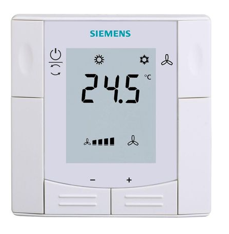
Siemens RDF660MB
Siemens
Controls a Siemens room thermostat via Modbus RTU
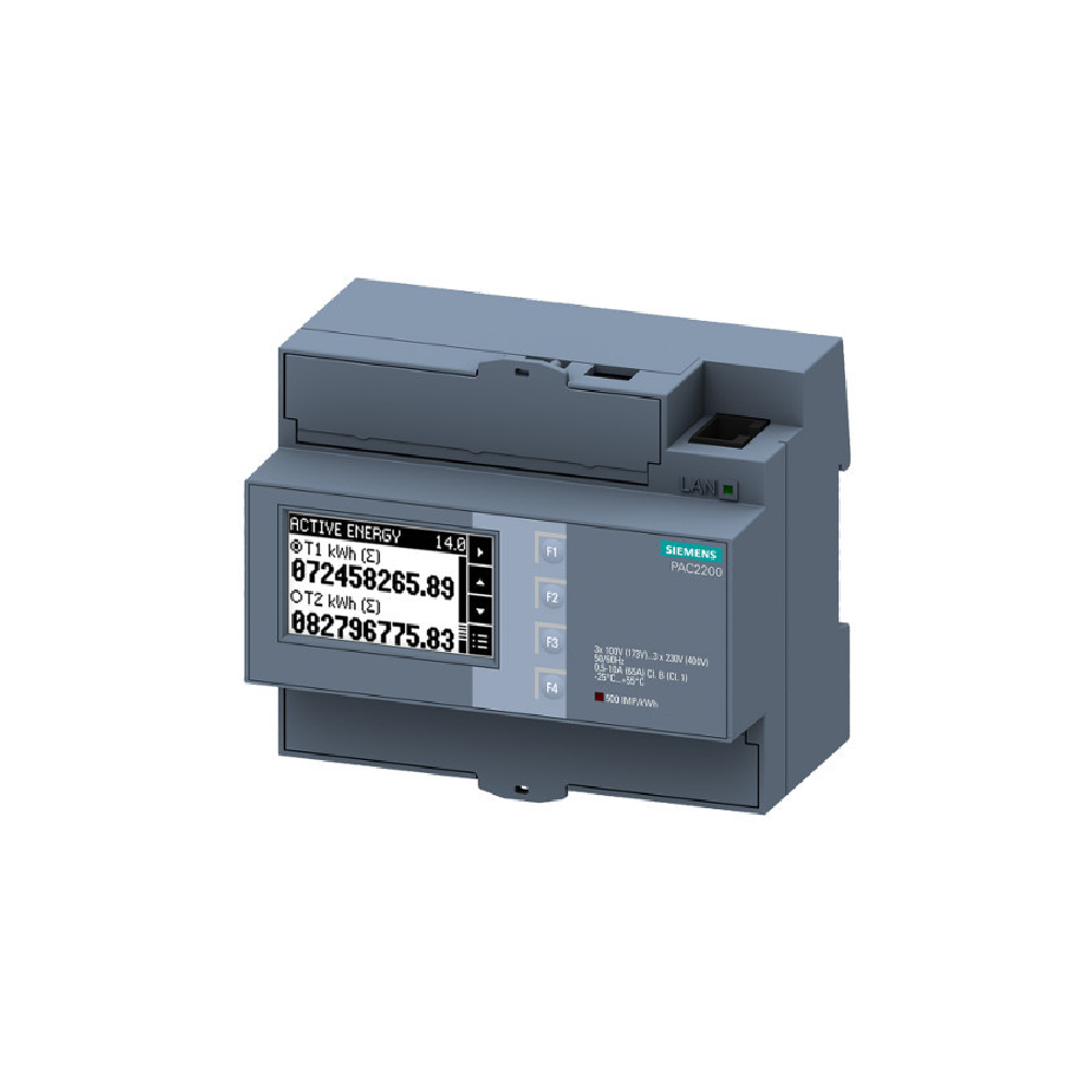
Siemens Sentron PAC 2200
Siemens
Monitors three-phase energy metering via Modbus TCP on Siemens Sentron PAC 2200.
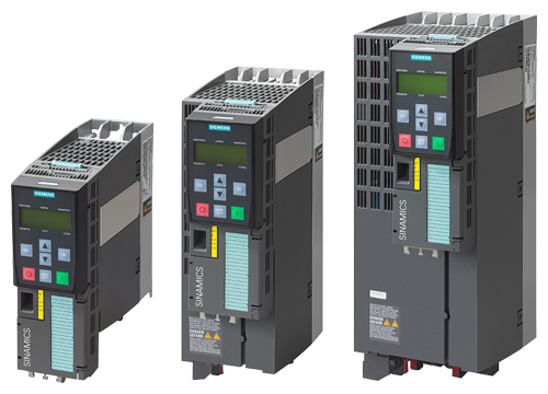
Siemens SINAMICS G120
Siemens
Frequency converter: speed, current, power, faults and remote start, stop and setpoint.
Siemens Sentron PAC3100 Power meter 3 phase
Siemens
Reads 3-phase power metering data from a Siemens Sentron PAC3100.
More RTU templates

Alnor HRU
Alnor Systemy Wentylacji Sp. z o. o.
Controls and monitors Alnor heat recovery ventilation units via Modbus RTU.

Alnor HRU-P
Alnor Systemy Wentylacji Sp. z o. o.
Controls Alnor HRU-P heat recovery ventilation units via Modbus RTU.

connecdoor.controller
connecdoor
Controls and monitors smart door access points via RS485
Wattsonic - Schmachtl Sun Energy Box
Wattsonic
Monitors Schmachtl Wattsonic hybrid inverter via Modbus RTU

Heidelberg Wallbox Energy Control
AMPERFIED GmbH
Controls and monitors Heidelberg Wallbox Energy Control EV charger via Modbus RTU.
Eastron SDM72D-M
Eastron
Reads energy metering values from an Eastron SDM72D-M three-phase meter.