









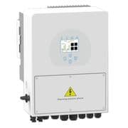
Sunsynk 3p hybrid inverter (battery)
The Sunsynk 3p hybrid inverter is a three-phase solar hybrid inverter that manages power flow between PV, battery storage, the grid, and loads in commercial and residential installations. This ModbusCloud template connects via Modbus RTU over RS-485 and reads battery power, cumulative energy, and state of charge, while also exposing the full set of battery-mode program registers for remote charge and discharge scheduling. For installers and facility managers, it enables continuous battery monitoring and automated schedule control from a single cloud portal.
- Protocol
- Modbus RTU
- Connection
- RS485
- Registers
- 14, read and write
- Brand
- Sunsynk
- Compatible models
- 3p hybrid inverter
- Last updated
Registers (14)
3 read, 11 write
| Name | Unit | Access | Address (Hidden until you enter your email) | Function (hidden) | Type (hidden) |
|---|---|---|---|---|---|
| power | W | Read | |||
| energy | Wh | Read | |||
| soc | % | Read | |||
| batterymode_a | Write | ||||
| batterymode_b | Write | ||||
| batterymode_c | Write | ||||
| batterymode_d | Write | ||||
| batterymode_e | Write | ||||
| batterymode_f | Write | ||||
| batterymode_g | Write | ||||
| batterymode_h | Write | ||||
| batterymode_i | Write | ||||
| batterymode_j | Write | ||||
| batterymode_t | Write |
Loading registers…
Send your device list
If a device is not in the library yet, we build the template for free as soon as we have the register data.
Use cases
- Monitor battery state of charge continuously to detect degradation or unexpected overnight discharge events.
- Track cumulative battery energy throughput over months to verify actual cycle use against design assumptions.
- Alert on battery power readings that exceed expected charge or discharge thresholds during off-peak periods.
- Compare live power register values against scheduled program setpoints to verify time-of-use control is active.
- Report battery mode configuration changes across multiple three-phase hybrid inverter sites from one dashboard.
Installation
Enable Modbus RTU on the Sunsynk 3p hybrid inverter via the inverter display under Advanced Settings, and set a unique Modbus unit ID for each inverter on the RS-485 bus.
Wire the RS-485 A and B terminals on the inverter to the ModbusCloud Gateway RS-485 port using a twisted-pair cable, keeping the cable run within the recommended length and adding a termination resistor only at the final device.
In your ModbusCloud portal, add the Gateway, import the Sunsynk 3p hybrid inverter (battery) template, and assign the Modbus unit ID that matches the setting on the inverter display.
Verify the connection by checking that the soc register at address 588 and the power register at address 590 return plausible live values in the portal dashboard before enabling any write registers.
Things to watch for
The soc and power registers return zero or frozen values. Why?
Check that the Modbus unit ID in the portal matches the ID configured on the inverter display under Advanced Settings. A mismatch causes the gateway to address the wrong device. Also confirm the RS-485 A and B wires are not swapped, as polarity reversal produces no response.
RS-485 communication is unstable or produces framing errors. What is wrong?
A 120-ohm termination resistor fitted at the ModbusCloud Gateway end can pull the RS-485 idle voltage below the inverter's detection threshold. Remove the termination resistor from the adapter side and test again. The DC idle voltage between A and B should read approximately 4 to 5 V with no traffic.
The energy register at address 518 shows an unexpectedly large or non-resetting value. Is this normal?
Address 518 is a 32-bit cumulative counter stored as uint32. It never resets unless the inverter firmware is re-initialised. Use the ModbusCloud portal's delta-calculation feature to derive interval energy from successive readings rather than expecting a daily-reset counter.
Is it safe to write to the batterymode registers repeatedly for automated scheduling?
Use caution. The batterymode registers (addresses 109, 127, 128, 130, 146, 166 to 171) write directly to inverter firmware storage. Excessive write frequency can accelerate flash memory wear. Write only when a setpoint change is actually required, not on every polling cycle, and validate each new value against the allowed range documented in the Sunsynk Modbus protocol before sending.
Want to see how it works?
