

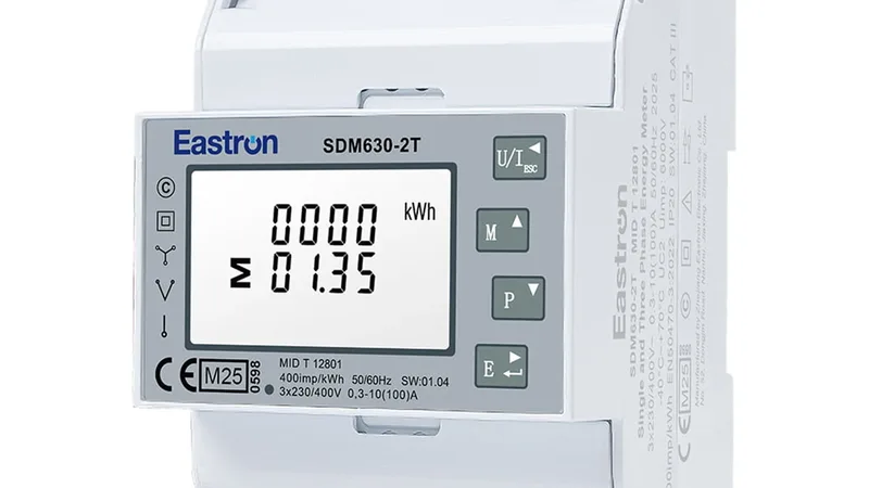

ZCS Azzurro 3PH HYD ZSS
Three-phase hybrid inverter with battery: reads PV, grid and battery values and sets storage mode and limits.
The ZCS Azzurro 3PH HYD ZSS is a three-phase hybrid inverter that converts solar power and charges and discharges a home or business battery. This Modbus RTU template reads PV, grid and battery values with energy counters and fault codes, and sets the storage mode and feed-in limit from ModbusCloud.
- Protocol
- Modbus RTU
- Connection
- RS485, 9600 baud
- Registers
- 197, read and write
- Brand
- ZCS Azzurro
- Key readings
- PV power · Grid power · Battery state of charge · Battery power · Energy imported and exported · Solar generation today · System state
- Available commands
- Energy storage mode · Remote on and off · Feed-in limit · Passive mode battery power
- Compatible models
- ZCS Azzurro 3PH HYD5000 to HYD20000 ZSS · SofarSolar HYD 5 to 20KTL-3PH
- Last updated
Registers (197)
188 read, 19 write
| Name | Unit | Access | Address (Hidden until you enter your email) | Function (hidden) | Type (hidden) |
|---|---|---|---|---|---|
| System State | Read | 1028 | FC03 | uint16 | |
| Fault 1 | Read | 1029 | FC03 | uint16 | |
| Fault 2 | Read | 1030 | FC03 | uint16 | |
| Fault 3 | Read | 1031 | FC03 | uint16 | |
| Fault 4 | Read | 1032 | FC03 | uint16 | |
| Fault 5 | Read | ||||
| Fault 6 | Read | ||||
| Fault 7 | Read | ||||
| Fault 8 | Read | ||||
| Fault 9 | Read | ||||
| Fault 10 | Read | ||||
| Fault 11 | Read | ||||
| Fault 12 | Read | ||||
| Waiting Time | s | Read | |||
| Inverter Temperature 1 | °C | Read | |||
| Inverter Temperature 2 | °C | Read | |||
| Heatsink Temperature 1 | °C | Read | |||
| Heatsink Temperature 2 | °C | Read | |||
| Module Temperature 1 | °C | Read | |||
| Module Temperature 2 | °C | Read | |||
| System Time Year | Read | ||||
| System Time Month | Read | ||||
| System Time Day | Read | ||||
| System Time Hour | Read | ||||
| System Time Minute | Read | ||||
| System Time Second | Read | ||||
| Serial Number | Read | ||||
| Hardware Version | Read | ||||
| Software Version | Read | ||||
| Grid Frequency | Hz | Read | |||
| Active Power Output Total | kW | Read | |||
| Reactive Power Output Total | var | Read | |||
| Apparent Power Output Total | VA | Read | |||
| Active Power PCC Total | kW | Read | |||
| Reactive Power PCC Total | var | Read | |||
| Apparent Power PCC Total | VA | Read | |||
| Voltage L1 | V | Read | |||
| Current Output L1 | A | Read | |||
| Active Power Output L1 | kW | Read | |||
| Reactive Power Output L1 | var | Read | |||
| Power Factor Output L1 | Read | ||||
| Current PCC L1 | A | Read | |||
| Active Power PCC L1 | kW | Read | |||
| Reactive Power PCC L1 | var | Read | |||
| Power Factor PCC L1 | Read | ||||
| Voltage L2 | V | Read | |||
| Current Output L2 | A | Read | |||
| Active Power Output L2 | kW | Read | |||
| Reactive Power Output L2 | var | Read | |||
| Power Factor Output L2 | Read | ||||
| Current PCC L2 | A | Read | |||
| Active Power PCC L2 | kW | Read | |||
| Reactive Power PCC L2 | var | Read | |||
| Power Factor PCC L2 | Read | ||||
| Voltage L3 | V | Read | |||
| Current Output L3 | A | Read | |||
| Active Power Output L3 | kW | Read | |||
| Reactive Power Output L3 | var | Read | |||
| Power Factor Output L3 | Read | ||||
| Current PCC L3 | A | Read | |||
| Active Power PCC L3 | kW | Read | |||
| Reactive Power PCC L3 | var | Read | |||
| Power Factor PCC L3 | Read | ||||
| Active Power PV Ext | kW | Read | |||
| Active Power Load Sys | kW | Read | |||
| Voltage Phase L1N | V | Read | |||
| Current Output L1N | A | Read | |||
| Active Power Output L1N | kW | Read | |||
| Current PCC L1N | A | Read | |||
| Active Power PCC L1N | kW | Read | |||
| Voltage Phase L2N | V | Read | |||
| Current Output L2N | A | Read | |||
| Active Power Output L2N | kW | Read | |||
| Current PCC L2N | A | Read | |||
| Active Power PCC L2N | kW | Read | |||
| Voltage Line L1 | V | Read | |||
| Voltage Line L2 | V | Read | |||
| Voltage Line L3 | V | Read | |||
| PV Voltage 1 | V | Read | |||
| PV Current 1 | A | Read | |||
| PV Power 1 | kW | Read | |||
| PV Voltage 2 | V | Read | |||
| PV Current 2 | A | Read | |||
| PV Power 2 | kW | Read | |||
| PV Power Total | kW | Read | |||
| Battery Voltage 1 | V | Read | |||
| Battery Current 1 | A | Read | |||
| Battery Power 1 | kW | Read | |||
| Battery Temperature 1 | °C | Read | |||
| Battery Capacity 1 | % | Read | |||
| Battery State of Health 1 | % | Read | |||
| Battery Charge Cycle 1 | Read | ||||
| Battery Voltage 2 | V | Read | |||
| Battery Current 2 | A | Read | |||
| Battery Power 2 | kW | Read | |||
| Battery Temperature 2 | °C | Read | |||
| Battery Capacity 2 | % | Read | |||
| Battery State of Health 2 | % | Read | |||
| Battery Charge Cycle 2 | Read | ||||
| Battery Voltage 3 | V | Read | |||
| Battery Current 3 | A | Read | |||
| Battery Power 3 | kW | Read | |||
| Battery Temperature 3 | °C | Read | |||
| Battery Capacity 3 | % | Read | |||
| Battery State of Health 3 | % | Read | |||
| Battery Charge Cycle 3 | Read | ||||
| Battery Voltage 4 | V | Read | |||
| Battery Current 4 | A | Read | |||
| Battery Power 4 | kW | Read | |||
| Battery Temperature 4 | °C | Read | |||
| Battery Capacity 4 | % | Read | |||
| Battery State of Health 4 | % | Read | |||
| Battery Charge Cycle 4 | Read | ||||
| Battery Voltage 5 | V | Read | |||
| Battery Current 5 | A | Read | |||
| Battery Power 5 | kW | Read | |||
| Battery Temperature 5 | °C | Read | |||
| Battery Capacity 5 | % | Read | |||
| Battery State of Health 5 | % | Read | |||
| Battery Charge Cycle 5 | Read | ||||
| Battery Voltage 6 | V | Read | |||
| Battery Current 6 | A | Read | |||
| Battery Power 6 | kW | Read | |||
| Battery Temperature 6 | °C | Read | |||
| Battery Capacity 6 | % | Read | |||
| Battery State of Health 6 | % | Read | |||
| Battery Charge Cycle 6 | Read | ||||
| Battery Voltage 7 | V | Read | |||
| Battery Current 7 | A | Read | |||
| Battery Power 7 | kW | Read | |||
| Battery Temperature 7 | °C | Read | |||
| Battery Capacity 7 | % | Read | |||
| Battery State of Health 7 | % | Read | |||
| Battery Charge Cycle 7 | Read | ||||
| Battery Voltage 8 | V | Read | |||
| Battery Current 8 | A | Read | |||
| Battery Power 8 | kW | Read | |||
| Battery Temperature 8 | °C | Read | |||
| Battery Capacity 8 | % | Read | |||
| Battery State of Health 8 | % | Read | |||
| Battery Charge Cycle 8 | Read | ||||
| Battery Power Total | kW | Read | |||
| Battery Capacity Total | % | Read | |||
| Battery State of Health Total | % | Read | |||
| Solar Generation Today | kWh | Read | |||
| Solar Generation Total | kWh | Read | |||
| Load Consumption Today | kWh | Read | |||
| Load Consumption Total | kWh | Read | |||
| Import Energy Today | kWh | Read | |||
| Import Energy Total | kWh | Read | |||
| Export Energy Today | kWh | Read | |||
| Export Energy Total | kWh | Read | |||
| Battery Input Energy Today | kWh | Read | |||
| Battery Input Energy Total | kWh | Read | |||
| Battery Output Energy Today | kWh | Read | |||
| Battery Output Energy Total | kWh | Read | |||
| System Time Update Result | Read and write | ||||
| Feed-In Limitation Mode | Read and write | ||||
| Feed-In Maximum Power | Read and write | ||||
| Battery Active Control | Read | ||||
| Battery Config ID | Read | ||||
| Battery Config Address 1 | Read | ||||
| Battery Config Protocol | Read | ||||
| Battery Config Overvoltage Protection | V | Read | |||
| Battery Config Charging Voltage | V | Read | |||
| Battery Config Undervoltage Protection | V | Read | |||
| Battery Config Minimum Discharge Voltage | V | Read | |||
| Battery Config Maximum Charge Current Limit | A | Read | |||
| Battery Config Maximum Discharge Current Limit | A | Read | |||
| Battery Config Depth of Discharge | % | Read | |||
| Battery Config End of Discharge | % | Read | |||
| Battery Config Capacity | Read | ||||
| Battery Config Rated Battery Voltage | V | Read | |||
| Battery Config Cell Type | Read | ||||
| Battery Config EPS Buffer | % | Read | |||
| Battery Config Address 2 | Read | ||||
| Battery Config Address 3 | Read | ||||
| Battery Config Address 4 | Read | ||||
| Battery Config Lead Acid Battery Temperature Compensation Factor | Read | ||||
| Battery Config Lead Acid Battery Recovery Buffer | V | Read | |||
| Battery Config Lead Acid Battery Float Voltage | V | Read | |||
| Remote Switch On Off | Read and write | ||||
| Energy Storage Mode | Read and write | ||||
| Passive Timeout | s | Read and write | |||
| Passive Timeout Action | Read and write | ||||
| Passive Desired Grid Power | W | Read and write | |||
| Passive Minimum Battery Power | W | Read and write | |||
| Passive Maximum Battery Power | W | Read and write | |||
| Set Time Year | Write | ||||
| Set Time Month | Write | ||||
| Set Time Day | Write | ||||
| Set Time Hour | Write | ||||
| Set Time Minute | Write | ||||
| Set Time Second | Write | ||||
| IV Curve Scan | Write | ||||
| EPS Control | Write | ||||
| EPS Wait Time | Write |
Loading registers…
Send your device list
If a device is not in the library yet, we build the template for free as soon as we have the register data.
Use cases
- Show solar power, grid import and export and battery charge on one ModbusCloud dashboard per site.
- Send an email when a fault register is not zero or the system state changes to a fault.
- Track daily solar generation and grid import in the history to compare months and seasons.
- Switch the energy storage mode from self use to time of use from the portal for a planned tariff.
- Set an alarm when battery state of health drops below a threshold you choose.
Installation
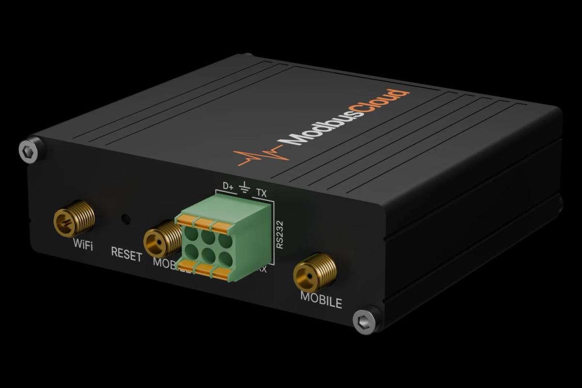
Connect RS485 A and B from the ModbusCloud Gateway to the communication port of the inverter, with a 120 ohm resistor at both ends of the bus.
In the inverter menu, check the Modbus address (1 by default) and the baud rate (9600).
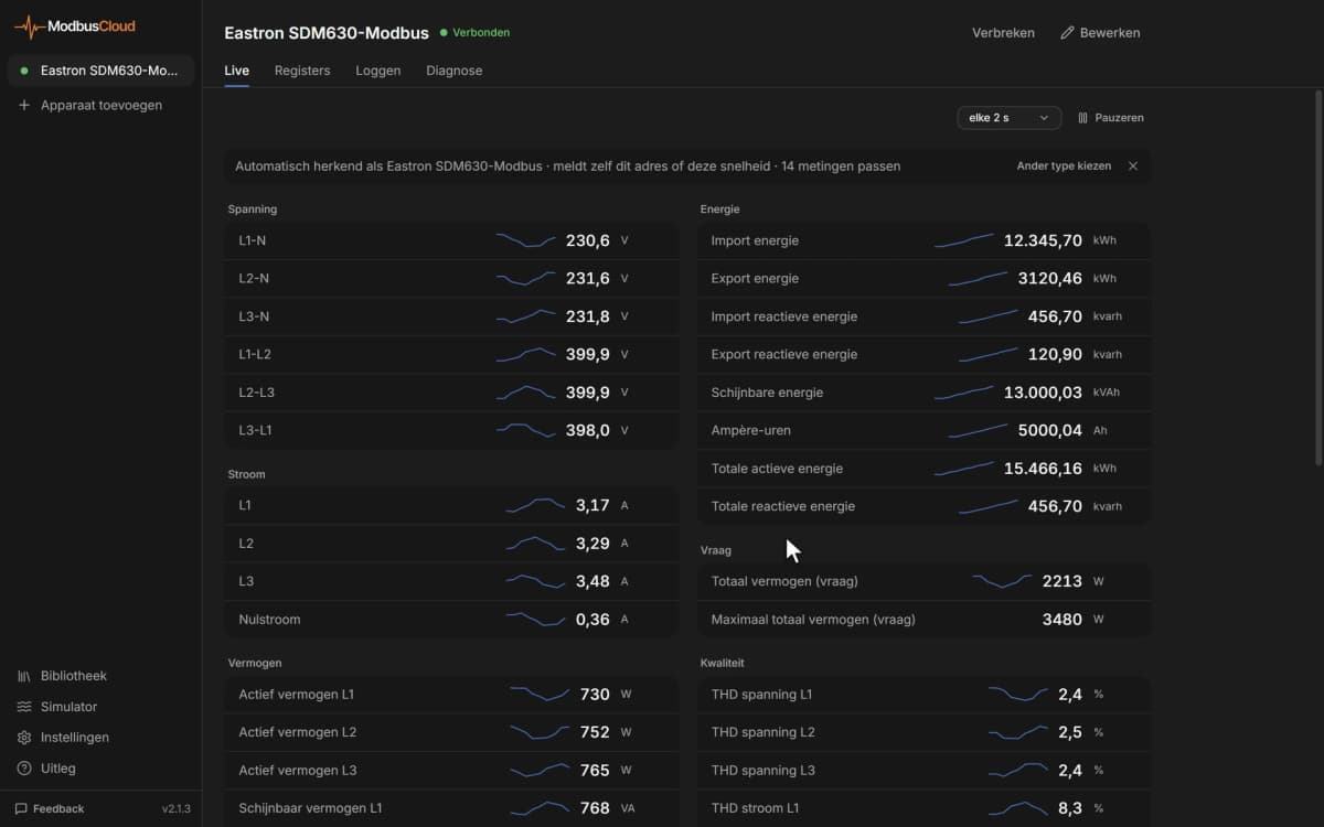
In ModbusCloud, add a Modbus RTU device with address 1, 9600 baud, 8N1, and import the ZCS Azzurro 3PH HYD ZSS template.
Check that PV power, grid power and battery state of charge come in and match the inverter display.
Things to watch for
The inverter does not answer on the RS485 bus. What should I check?
Check that A and B are not swapped, that the address in the inverter menu matches the one in ModbusCloud and that both sides use 9600 baud 8N1. Fit a 120 ohm resistor at both ends of a longer bus. A data logger on the same port can block the bus.
Why does power show 0.05 instead of 50 watts?
Most power values come in kilowatts with two decimals, so 0.05 means 50 W. Battery power total and PV power total use one decimal in kilowatts. Reactive and apparent power use the same scaling and are probably in kvar and kVA.
How do I change the energy storage mode or the feed-in limit?
Write the new value to Energy Storage Mode or to the Feed-In registers. The inverter expects settings that belong together, such as the feed-in mode and maximum power or the three passive mode powers, in one write. Read the current values first and change one setting at a time.
Battery values show zero for battery inputs 2 to 8.
Only the battery inputs that are connected and configured return values. With one battery stack, its values are under battery 1 and the totals; the other inputs stay at zero.

Want to see how it works?