








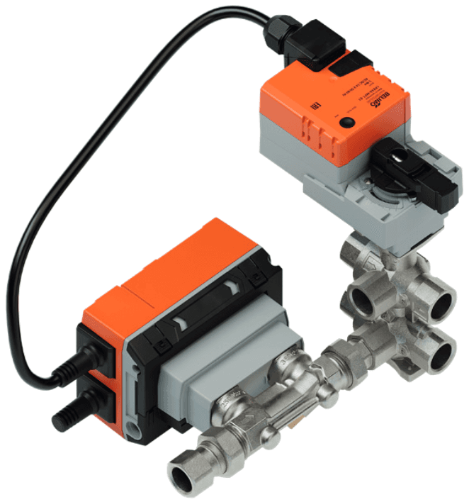
Belimo 6-way EPIV V4 Modbus RTU
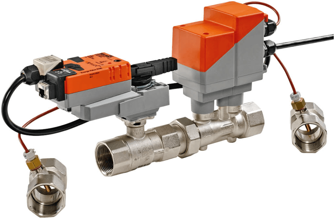
Controls 6-way pressure-independent valves with ultrasonic flow measurement and condensation monitoring.
Template for the Belimo 6-way EPIV V4 characterised control valve over Modbus RTU. Reads valve position, volumetric flow, temperature, humidity, condensation status, and accumulated volume. Controls setpoints per sequence, flow limits, control mode, and condensation protection settings.
- Protocol
- Modbus RTU
- Connection
- RS485, 38400 baud
- Registers
- 58, read and write
- Brand
- Belimo
- Key readings
- Relative and absolute position · Relative and absolute volumetric flow · Flow body temperature · Accumulated volume · Relative humidity · Condensation protection status
- Available commands
- Setpoint relative per sequence · Control mode and setpoint source · Max flow limit per sequence · Condensation protection settings
- Compatible models
- EP..R6+BAC · EP..R6+BAC-HH1 · EP..R6+BAC-HH2 · EP..R6+BAC-HHM
- Last updated
Registers (58)
32 read, 26 write
| Name | Unit | Access | Address (Hidden until you enter your email) | Function (hidden) | Type (hidden) |
|---|---|---|---|---|---|
| Relative position | % | Read | |||
| Absolute position | °C | Read | |||
| Relative volumetric flow | % | Read | |||
| Absolute volumetric flow in selected unit | l/h | Read | |||
| Setpoint analog | % | Read | |||
| Temperature (flow body) in Celcius | °C | Read | |||
| Temperature (flow body) in Fahrenheit | °F | Read | |||
| Glycol concentration | % | Read | |||
| Series number 1st part | Read | ||||
| Series number 2nd part | Read | ||||
| Series number 4th part | Read | ||||
| Firmware version | Read | ||||
| Error state | Read | ||||
| Absolute volumetric flow in liter per second | l/s | Read | |||
| Absolute volumetric flow in gpm | gpm | Read | |||
| Setpoint absolute flow in selected unit | l/h | Read | |||
| Nominal volumetric flow in selected unit | l/h | Read | |||
| Nominal volumetric flow in liter per second | l/s | Read | |||
| Nominal volumetric flow in gpm | gpm | Read | |||
| Sensor 1 value | mV | Read | |||
| Setpoint absolute flow in liter per second | l/s | Read | |||
| Setpoint absolute flow in gpm | gpm | Read | |||
| Accumulated volume in cubic meter | m³ | Read | |||
| Accumulated volume in gallon | gal | Read | |||
| Accumulated volume in selected unit | l/h | Read | |||
| Bus Termination | Read | ||||
| Flow meter serial number first digits | Read | ||||
| Flow meter serial number last digits | Read | ||||
| Device Type | Read | ||||
| Actual sequence | Read | ||||
| Relative humidity | % | Read | |||
| Condensation protection status | Read | ||||
| Setpoint relative | % | Write | |||
| Override control | Write | ||||
| Control Mode | Write | ||||
| Unit Selection Flow | Write | ||||
| Setpoint source | Write | ||||
| Command | Write | ||||
| Timeout for bus watchdog | s | Write | |||
| Bus fail action | Write | ||||
| Sensor 1 type | Write | ||||
| Unit Selection Volume | Write | ||||
| Setpoint relative for sequence 1 | % | Write | |||
| Setpoint relative for sequence 2 | % | Write | |||
| Setpoint mode | Write | ||||
| Invert sequences | Write | ||||
| Max. flow limit for sequence 1 in percent | % | Write | |||
| Max. flow limit for sequence 2 in percent | % | Write | |||
| Max. flow limit for sequence 1 in liter per second | l/s | Write | |||
| Max. flow limit for sequence 1 in gpm | gpm | Write | |||
| Max. flow limit for sequence 1 in selected unit | l/h | Write | |||
| Max. flow limit for sequence 2 in liter per second | l/s | Write | |||
| Max. flow limit for sequence 2 in gpm | gpm | Write | |||
| Max. flow limit for sequence 2 in selected unit | l/h | Write | |||
| Enable condensation protection | Write | ||||
| Condensation protection action | Write | ||||
| Condensation warning threshold | % | Write | |||
| Condensation action delay | s | Write |
Loading registers…
Send your device list
If a device is not in the library yet, we build the template for free as soon as we have the register data.
Use cases
- Monitor real-time volumetric flow and valve position on a live dashboard to verify hydronic balancing across zones.
- Create an alert when condensation protection activates so the installer can investigate cooling circuit conditions remotely.
- Log accumulated volume per zone over time to analyse energy consumption patterns for heating and cooling.
- Adjust maximum flow limits per sequence remotely to optimise comfort without a site visit.
- Switch between heating and cooling setpoints based on room demand and schedule from the cloud interface.
- Verify correct commissioning by comparing measured flow against design flow for each sequence after installation.
Installation
Wire the Belimo EPIV actuator RS-485 terminals (A, B, GND) to the corresponding terminals on the ModbusCloud Gateway.
Set the Modbus slave address on the actuator using the Belimo Assistant 2 app via NFC or through the on-device interface.
Confirm the baud rate is set to 38400 on both the actuator and the gateway serial port configuration.
Import the Belimo 6-way EPIV V4 template in the ModbusCloud platform and assign it to the correct gateway and serial port.
Select the desired flow unit (l/s, gpm, or l/h) in the unit selection registers to match your project requirements.
Power up the system and verify live data appears on the ModbusCloud dashboard before closing the installation.
Things to watch for
Why do I see zero or incorrect values for flow and accumulated volume registers?
These registers are uint32 values spanning two consecutive Modbus addresses. Make sure the template is correctly mapping both addresses. Also verify the byte order setting on the gateway matches the Belimo default (big-endian).
What baud rate should I use for the Belimo 6-way EPIV?
The default baud rate for this template is 38400. Both the actuator and the ModbusCloud gateway serial port must be configured to 38400 with matching parity and stop bit settings.
Can I mix multiple Belimo EPIV actuators on one RS-485 bus?
Yes. Each actuator must have a unique Modbus slave address. Use the Belimo Assistant 2 app to set the address on each device before connecting them to the shared bus.
How does condensation protection work through Modbus?
The actuator monitors relative humidity and flow body temperature internally. The template reads the condensation protection status register and allows you to adjust protection settings. Set up an alert in ModbusCloud to be notified when condensation risk is detected.
Want to see how it works?
