








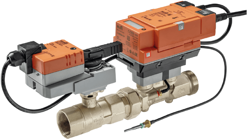
Belimo Energy Valve V4 Modbus TCP
Monitors and controls energy valves with integrated flow, power, and temperature measurement
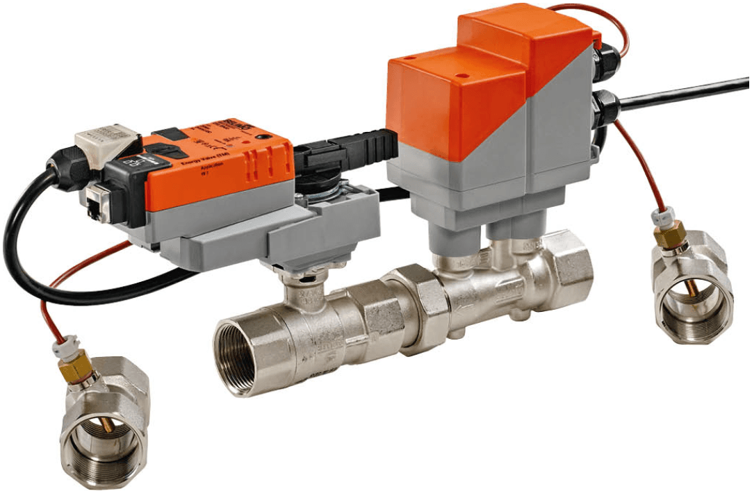
Template for the Belimo Energy Valve V4 via Modbus TCP. Reads volumetric flow, thermal power, heating and cooling energy totals, temperatures, delta-T, and differential pressure. Also provides setpoint control for valve position, flow limits, and delta-T.
- Protocol
- Modbus TCP
- Connection
- Ethernet, Modbus TCP
- Registers
- 98, read and write
- Brand
- Belimo
- Key readings
- Temperature 1 and 2 · Volumetric flow · Heating and cooling power · Heating and cooling energy totals · Delta-T · Differential water pressure
- Available commands
- Setpoint position · Control mode · Vmax and Vmin limits · Setpoint delta-T
- Compatible models
- EV..R2+(K)BAC · EV..R2+MID · EV..R3+BAC
- Last updated
Registers (98)
62 read, 36 write
| Name | Unit | Access | Address (Hidden until you enter your email) | Function (hidden) | Type (hidden) |
|---|---|---|---|---|---|
| Actuator type | Read | ||||
| Relative position | % | Read | |||
| Absolute position | °C | Read | |||
| Relative volumetric flow | % | Read | |||
| Absolute volumetric flow in selected unit | l/h | Read | |||
| Setpoint analog | % | Read | |||
| Temperature 1 in degree Celsius | °C | Read | |||
| Temperature 1 in degree Fahrenheit | °F | Read | |||
| Temperature 2 in degree Celsius | °C | Read | |||
| Temperature 2 in degree Fahrenheit | °F | Read | |||
| DeltaT_K | K | Read | |||
| DeltaT_F | °F | Read | |||
| Glycol concentration | % | Read | |||
| Relative power | % | Read | |||
| Series Number 1st part | Read | ||||
| Series Number 2nd part | Read | ||||
| Series Number 4th part | Read | ||||
| Firmware version | Read | ||||
| Error state | Read | ||||
| DeltaT Manager Status | Read | ||||
| Absolute volumetric flow in liter per second | l/s | Read | |||
| Absolute volumetric flow in gpm | gpm | Read | |||
| Setpoint flow in selected unit | l/h | Read | |||
| Absolute Power Cooling in selected unit | kW | Read | |||
| Absolute Power Cooling in kW | kW | Read | |||
| Absolute Power Cooling in kBtu per hour | kBtu/h | Read | |||
| Energy Cooling in selected unit | kWh | Read | |||
| Energy Cooling in kWh | kWh | Read | |||
| Energy Cooling in kBtu | kBtu | Read | |||
| Energy Heating in selected unit | kWh | Read | |||
| Energy Heating in kWh | kWh | Read | |||
| Energy Heating in kBtu | kBtu | Read | |||
| Nominal volumetric flow in selected unit | l/h | Read | |||
| Nominal volumetric flow in liter per second | l/s | Read | |||
| Nominal volumetric flow in gpm | gpm | Read | |||
| Nominal power in selected unit | kW | Read | |||
| Nominal power in kW | kW | Read | |||
| Nominal power in kBtu per hour | kBtu/h | Read | |||
| Setpoint flow in liter per second | l/s | Read | |||
| Setpoint flow in gpm | gpm | Read | |||
| Absolute Power Heating in kW | kW | Read | |||
| Absolute Power Heating in kBtu per hour | kBtu/h | Read | |||
| Absolute Power Heating in selected unit | kW | Read | |||
| Sensor Serial Number 1st Part | Read | ||||
| Sensor Serial Number 2nd Part | Read | ||||
| Sensor value 1 | Read | ||||
| Sensor 1 value in degree Celcius | °C | Read | |||
| Sensor 1 value in degree Fahrenheit | °F | Read | |||
| Total volume in cubic meter | m³ | Read | |||
| Total volume in gallon | gal | Read | |||
| Total volume in selected unit | m³ | Read | |||
| Bus termination | Read | ||||
| Absolute differential water pressure in selected unit | bar | Read | |||
| Relative water differential pressure | % | Read | |||
| Absolute differential water pressure in psi | psi | Read | |||
| Absolute differential water pressure in kPa | kPa | Read | |||
| Status of the differential water pressure sensor | Read | ||||
| Differential water pressure control status | Read | ||||
| Nominal differential water pressure in selected unit | bar | Read | |||
| Nominal differential water pressure in psi | psi | Read | |||
| Nominal differential water pressure in kPa | kPa | Read | |||
| Malfunction and service information | Read | ||||
| Setpoint | % | Write | |||
| Override control | Write | ||||
| Vmax in percent of Vnom | % | Write | |||
| Pmax in percent of Pnom | % | Write | |||
| Delta T Limitation | Write | ||||
| Setpoint DeltaT in K | K | Write | |||
| Setpoint DeltaT in F | °F | Write | |||
| Control Mode | Write | ||||
| Unit Selection Flow | Write | ||||
| Unit Selection Power | Write | ||||
| Unit Selection Energy | Write | ||||
| Setpoint Source | Write | ||||
| Absolute Vmax in liter per second | l/s | Write | |||
| Absolute Vmax in gpm | gpm | Write | |||
| Absolute Pmax in kW | kW | Write | |||
| Absolute Pmax in kBtu per hour | kBtu/h | Write | |||
| Vmin in percent of Vmax | % | Write | |||
| Absolute Vmax in selected unit | l/h | Write | |||
| Absolute Vmin in liter per second | l/s | Write | |||
| Absolute Vmin in gpm | gpm | Write | |||
| Absolute Vmin in selected unit | l/h | Write | |||
| Absolute Pmax in selected unit | kW | Write | |||
| Unit Selection Volume | Write | ||||
| Select Meter Register | Write | ||||
| Command | Write | ||||
| Setpoint Flow at DeltaT in liter per second | l/s | Write | |||
| Setpoint Flow at DeltaT in gpm | gpm | Write | |||
| Setpoint Flow at DeltaT in selected unit | l/h | Write | |||
| Communication Watchdog | Write | ||||
| Sensor 1 Type | Write | ||||
| Sensor 1 Passive Sensor Type | Write | ||||
| Unit selection pressure difference | Write | ||||
| Absolute differential water pressure setpoint in selected unit | bar | Write | |||
| Absolute differential water pressure setpoint in psi | psi | Write | |||
| Absolute differential water pressure setpoint in kPa | kPa | Write | |||
| Bus watchdog fail action | Write |
Loading registers…
Send your device list
If a device is not in the library yet, we build the template for free as soon as we have the register data.
Use cases
- Monitor heating and cooling energy totals per zone on a live cloud dashboard for your customer.
- Create an alert when delta-T drops below a threshold, indicating poor heat transfer or bypass flow.
- Log volumetric flow and thermal power over time to identify oversized or undersized distribution circuits.
- Remotely adjust Vmax and Vmin flow limits to optimize system balancing without a site visit.
- Compare supply and return temperatures across multiple Energy Valves to verify hydraulic balance.
- Track cumulative energy consumption per consumer for tenant billing or energy reporting.
Installation
Connect the Belimo Energy Valve V4 to the local network and ensure it has a valid IP address reachable by the ModbusCloud gateway.
Set the Modbus TCP unit ID on the Energy Valve V4 using the Belimo Assistant App or the device display, and note the IP address and port (default 502).
Wire the ModbusCloud Gateway to the same network segment, ensuring it can reach the Energy Valve IP address.
In the ModbusCloud portal, add a new device connection using the Energy Valve's IP address, TCP port, and unit ID.
Import the Belimo Energy Valve V4 Modbus TCP template from the ModbusCloud template library and assign it to the device connection.
Verify that live readings for temperatures, flow, and power appear on the dashboard, and confirm that unit selection registers are set to metric or imperial as required.
Things to watch for
Why do energy or flow readings show unexpected values?
Check the unit selection registers on the Energy Valve. The device supports both metric and imperial units, and the template expects a specific setting. Also verify glycol concentration, as a glycol mixture affects energy calculations.
Which Modbus TCP port and unit ID should I use?
The default Modbus TCP port is 502. The unit ID is configurable on the Energy Valve via the Belimo Assistant App or the device menu. Make sure the unit ID in ModbusCloud matches the valve setting.
Some registers return zero or do not update. What should I check?
The register map uses mixed data types including uint16, uint32, int16, and int32. Ensure the template is correctly matched to your valve variant (MID, BAC, or KBAC). Also confirm the valve firmware is up to date via the Belimo Assistant App.
Can I connect multiple Energy Valves to one ModbusCloud gateway?
Yes. Each valve needs a unique IP address on the network. Add a separate device connection in ModbusCloud for each valve, using the same template but different IP addresses and unit IDs.
Want to see how it works?
