








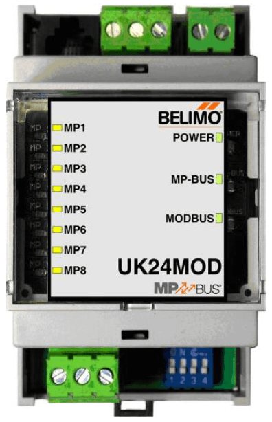
Belimo UK24MOD Modbus RTU
Bridges MP-Bus actuators to Modbus RTU for digital control and status monitoring.
The Belimo UK24MOD is a gateway that bridges up to 8 Belimo MP-Bus actuators to a Modbus RTU network. This template exposes actuator positions, volumetric flow rates, sensor values, error states, and provides setpoint and override control for each connected device.
- Protocol
- Modbus RTU
- Connection
- RS485, 38400 baud
- Registers
- 139, read and write
- Brand
- Belimo
- Key readings
- Actual Position MP1 to MP8 · Relative Volumetric Flow MP1 to MP8 · Absolute Volumetric Flow MP1 to MP8 · Nominal Volumetric Flow MP1 to MP8 · Sensor Value MP1 to MP8 · Errors and Malfunction MP1 to MP8
- Available commands
- Setpoint MP1 to MP8 · Override Control MP1 to MP8 · Min/Max Limits MP1 to MP8 · Command MP1 to MP8
- Compatible models
- UK24MOD
- Last updated
Registers (139)
90 read, 49 write
| Name | Unit | Access | Address (Hidden until you enter your email) | Function (hidden) | Type (hidden) |
|---|---|---|---|---|---|
| MP1 Actuator Type | Read | ||||
| MP1 Actual Position | % | Read | |||
| MP1 Sensor Value | Read | ||||
| MP1 Series Number 1st Part | Read | ||||
| MP1 Series Number 2nd Part | Read | ||||
| MP1 Series Number 4th Part | Read | ||||
| Firmware Version | Read | ||||
| MP1 Errors and Malfunction | Read | ||||
| MP1 Relative volumetric flow | % | Read | |||
| MP1 Absolute volumetric flow | m³/h | Read | |||
| MP1 Nominal volumetric flow | m³/h | Read | |||
| MP1 Time monitoring in s | s | Read | |||
| Modbus baud rate | Read | ||||
| Modbus adress | Read | ||||
| MP2 Absolute volumetric flow | m³/h | Read | |||
| MP3 Absolute volumetric flow | m³/h | Read | |||
| MP4 Absolute volumetric flow | m³/h | Read | |||
| MP5 Absolute volumetric flow | m³/h | Read | |||
| MP6 Absolute volumetric flow | m³/h | Read | |||
| MP7 Absolute volumetric flow | m³/h | Read | |||
| MP8 Absolute volumetric flow | m³/h | Read | |||
| MP2 Actual Position | % | Read | |||
| MP3 Actual Position | % | Read | |||
| MP4 Actual Position | % | Read | |||
| MP5 Actual Position | % | Read | |||
| MP6 Actual Position | % | Read | |||
| MP7 Actual Position | % | Read | |||
| MP8 Actual Position | % | Read | |||
| MP2 Actuator Type | Read | ||||
| MP3 Actuator Type | Read | ||||
| MP4 Actuator Type | Read | ||||
| MP5 Actuator Type | Read | ||||
| MP6 Actuator Type | Read | ||||
| MP7 Actuator Type | Read | ||||
| MP8 Actuator Type | Read | ||||
| MP2 Errors and Malfunction | Read | ||||
| MP3 Errors and Malfunction | Read | ||||
| MP4 Errors and Malfunction | Read | ||||
| MP5 Errors and Malfunction | Read | ||||
| MP6 Errors and Malfunction | Read | ||||
| MP7 Errors and Malfunction | Read | ||||
| MP8 Errors and Malfunction | Read | ||||
| MP2 Nominal volumetric flow | m³/h | Read | |||
| MP3 Nominal volumetric flow | m³/h | Read | |||
| MP4 Nominal volumetric flow | m³/h | Read | |||
| MP5 Nominal volumetric flow | m³/h | Read | |||
| MP6 Nominal volumetric flow | m³/h | Read | |||
| MP7 Nominal volumetric flow | m³/h | Read | |||
| MP8 Nominal volumetric flow | m³/h | Read | |||
| MP2 Relative volumetric flow | % | Read | |||
| MP3 Relative volumetric flow | % | Read | |||
| MP4 Relative volumetric flow | % | Read | |||
| MP5 Relative volumetric flow | % | Read | |||
| MP6 Relative volumetric flow | % | Read | |||
| MP7 Relative volumetric flow | % | Read | |||
| MP8 Relative volumetric flow | % | Read | |||
| MP2 Sensor Value | Read | ||||
| MP3 Sensor Value | Read | ||||
| MP4 Sensor value | Read | ||||
| MP5 Sensor Value | Read | ||||
| MP6 Sensor Value | Read | ||||
| MP7 Sensor Value | Read | ||||
| MP8 Sensor Value | Read | ||||
| MP2 Series Number 1st Part | Read | ||||
| MP3 Series Number 1st Part | Read | ||||
| MP4 Series Number 1st Part | Read | ||||
| MP5 Series Number 1st Part | Read | ||||
| MP6 Series Number 1st Part | Read | ||||
| MP7 Series Number 1st Part | Read | ||||
| MP8 Series Number 1st Part | Read | ||||
| MP2 Series Number 2nd Part | Read | ||||
| MP3 Series Number 2nd Part | Read | ||||
| MP4 Series Number 2nd Part | Read | ||||
| MP5 Series Number 2nd Part | Read | ||||
| MP6 Series Number 2nd Part | Read | ||||
| MP7 Series Number 2nd Part | Read | ||||
| MP8 Series Number 2nd Part | Read | ||||
| MP2 Series Number 4th Part | Read | ||||
| MP3 Series Number 4th Part | Read | ||||
| MP4 Series Number 4th Part | Read | ||||
| MP5 Series Number 4th Part | Read | ||||
| MP7 Series Number 4th Part | Read | ||||
| MP8 Series Number 4th Part | Read | ||||
| MP2 Time monitoring in s | s | Read | |||
| MP3 Time monitoring in s | s | Read | |||
| MP4 Time monitoring in s | s | Read | |||
| MP5 Time monitoring in s | s | Read | |||
| MP6 Time monitoring in s | s | Read | |||
| MP7 Time monitoring in s | s | Read | |||
| MP8 Time monitoring in s | s | Read | |||
| MP1 Setpoint | % | Write | |||
| MP1 Override Control | Write | ||||
| MP1 Command | Write | ||||
| MP1 Minimum | % | Write | |||
| MP1 Maximum | % | Write | |||
| MP1 Sensor Type | Write | ||||
| Response delay | ms | Write | |||
| MP2 Command | Write | ||||
| MP3 Command | Write | ||||
| MP4 Command | Write | ||||
| MP5 Command | Write | ||||
| MP6 Command | Write | ||||
| MP7 Command | Write | ||||
| MP8 Command | Write | ||||
| MP2 Maximum | % | Write | |||
| MP3 Maximum | % | Write | |||
| MP4 Maximum | % | Write | |||
| MP5 Maximum | % | Write | |||
| MP6 Maximum | % | Write | |||
| MP7 Maximum | % | Write | |||
| MP8 Maximum | % | Write | |||
| MP2 Minimum | % | Write | |||
| MP3 Minimum | % | Write | |||
| MP4 Minimum | % | Write | |||
| MP5 Minimum | % | Write | |||
| MP6 Minimum | % | Write | |||
| MP7 Minimum | % | Write | |||
| MP8 Minimum | % | Write | |||
| MP2 Override Control | Write | ||||
| MP3 Override Control | Write | ||||
| MP4 Override Control | Write | ||||
| MP5 Override Control | Write | ||||
| MP6 Override Control | Write | ||||
| MP7 Override Control | Write | ||||
| MP8 Override Control | Write | ||||
| MP2 Sensor Type | Write | ||||
| MP3 Sensor Type | Write | ||||
| MP4 Sensor Type | Write | ||||
| MP5 Sensor Type | Write | ||||
| MP6 Sensor Type | Write | ||||
| MP7 Sensor Type | Write | ||||
| MP8 Sensor Type | Write | ||||
| MP2 Setpoint | % | Write | |||
| MP3 Setpoint | % | Write | |||
| MP4 Setpoint | % | Write | |||
| MP5 Setpoint | % | Write | |||
| MP6 Setpoint | % | Write | |||
| MP7 Setpoint | % | Write | |||
| MP8 Setpoint | % | Write |
Loading registers…
Send your device list
If a device is not in the library yet, we build the template for free as soon as we have the register data.
Use cases
- Monitor actual actuator positions and volumetric flow rates for up to 8 Belimo MP-Bus devices on a live cloud dashboard.
- Create alerts when an actuator reports an error or malfunction state to reduce on-site diagnostic time.
- Adjust airflow or water flow setpoints remotely for VAV controllers and valve actuators during commissioning.
- Log relative and absolute volumetric flow data over time to verify HVAC system balancing and performance.
- Set min/max flow limits for each actuator channel to enforce design specifications from the cloud.
- Use override control registers to temporarily force actuator positions during maintenance or testing.
Installation
Wire the Belimo UK24MOD RS-485 terminals (A, B, GND) to the corresponding terminals on your ModbusCloud Gateway, observing correct polarity.
Connect the MP-Bus actuators (up to 8) to the UK24MOD MP-Bus terminals according to the Belimo wiring diagram.
Set the Modbus slave address on the UK24MOD using its configuration interface, and ensure it does not conflict with other devices on the bus.
Confirm the baud rate on the UK24MOD is set to 38400, matching the ModbusCloud gateway port configuration.
Import the Belimo UK24MOD template in the ModbusCloud platform and assign it to the correct gateway and Modbus address.
Verify that actuator positions, flow values, and error states appear on the dashboard for each connected MP-Bus channel.
Things to watch for
Why am I not getting any data from the UK24MOD?
Check that the RS-485 wiring polarity (A/B) is correct and that the baud rate on both the gateway and the UK24MOD is set to 38400. Also verify that the Modbus slave address in the template matches the address configured on the device.
I only see data for some MP-Bus channels. What is wrong?
Each MP-Bus device must be properly connected and recognized by the UK24MOD before its registers become active. Verify the MP-Bus wiring for the missing channels and check for actuator errors using the UK24MOD diagnostic LED or error registers.
What is the register layout for multiple actuators?
Each MP-Bus device (MP1 through MP8) occupies a block of registers offset by 20 addresses from the previous one. All registers are uint16. The template already accounts for this structure.
Can I mix different types of Belimo MP-Bus actuators on one UK24MOD?
Yes, the UK24MOD supports different actuator types on its MP-Bus channels. However, not all register values (such as volumetric flow) are relevant for every actuator type. Unused registers may return zero or default values.
Want to see how it works?
