


Janitza UMG 605-PRO averaging times, time stamps and maximum mean values
When each minimum and maximum occurred, and the largest mean values, on the UMG 605-PRO analyser.
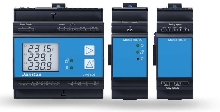
The Janitza UMG 605-PRO is a power quality analyser that measures voltage, current, power, harmonics and flicker on four channels. This Modbus RTU template reads the largest mean values, the moment each minimum and maximum occurred, and the averaging time of each mean value in ModbusCloud.
- Protocol
- Modbus RTU
- Connection
- RS485, 19200 baud
- Registers
- 763, read only
- Brand
- Janitza
- Key readings
- Largest mean values · Time of each maximum · Time of each minimum · Time of each largest mean value · Averaging time per mean value
- Compatible models
- UMG 605-PRO
- Last updated
Registers (763)
763 read, 0 write
| Name | Unit | Access | Address (Hidden until you enter your email) | Function (hidden) | Type (hidden) |
|---|---|---|---|---|---|
| Voltage L1-N Averaging Time | Read | ||||
| Voltage L2-N Averaging Time | Read | ||||
| Voltage L3-N Averaging Time | Read | ||||
| Voltage L4-N Averaging Time | Read | ||||
| Voltage L1-L2 Averaging Time | Read | ||||
| Voltage L2-L3 Averaging Time | Read | ||||
| Voltage L3-L1 Averaging Time | Read | ||||
| Voltage Crest Factor L1-N Averaging Time | Read | ||||
| Voltage Crest Factor L2-N Averaging Time | Read | ||||
| Voltage Crest Factor L3-N Averaging Time | Read | ||||
| Voltage Crest Factor L4-N Averaging Time | Read | ||||
| Voltage Crest Factor L1-L2 Averaging Time | Read | ||||
| Voltage Crest Factor L2-L3 Averaging Time | Read | ||||
| Voltage Crest Factor L3-L1 Averaging Time | Read | ||||
| Voltage Zero Sequence Averaging Time | Read | ||||
| Voltage Positive Sequence Averaging Time | Read | ||||
| Voltage Negative Sequence Averaging Time | Read | ||||
| Voltage Ripple Control Signal L1-N Averaging Time | Read | ||||
| Voltage Ripple Control Signal L2-N Averaging Time | Read | ||||
| Voltage Ripple Control Signal L3-N Averaging Time | Read | ||||
| Voltage Ripple Control Signal L4-N Averaging Time | Read | ||||
| Voltage THD L1-N Averaging Time | Read | ||||
| Voltage THD L2-N Averaging Time | Read | ||||
| Voltage THD L3-N Averaging Time | Read | ||||
| Voltage THD L4-N Averaging Time | Read | ||||
| Voltage Interharmonics THD L1-N Averaging Time | Read | ||||
| Voltage Interharmonics THD L2-N Averaging Time | Read | ||||
| Voltage Interharmonics THD L3-N Averaging Time | Read | ||||
| Voltage Interharmonics THD L4-N Averaging Time | Read | ||||
| Voltage Over Deviation L1-N Averaging Time | Read | ||||
| Voltage Over Deviation L2-N Averaging Time | Read | ||||
| Voltage Over Deviation L3-N Averaging Time | Read | ||||
| Voltage Over Deviation L4-N Averaging Time | Read | ||||
| Voltage Under Deviation L1-N Averaging Time | Read | ||||
| Voltage Under Deviation L2-N Averaging Time | Read | ||||
| Voltage Under Deviation L3-N Averaging Time | Read | ||||
| Voltage Under Deviation L4-N Averaging Time | Read | ||||
| Voltage Negative Peak L1-N Averaging Time | Read | ||||
| Voltage Negative Peak L2-N Averaging Time | Read | ||||
| Voltage Negative Peak L3-N Averaging Time | Read | ||||
| Voltage Negative Peak L4-N Averaging Time | Read | ||||
| Voltage Positive Peak L1-N Averaging Time | Read | ||||
| Voltage Positive Peak L2-N Averaging Time | Read | ||||
| Voltage Positive Peak L3-N Averaging Time | Read | ||||
| Voltage Positive Peak L4-N Averaging Time | Read | ||||
| Voltage Peak to Peak L1-N Averaging Time | Read | ||||
| Voltage Peak to Peak L2-N Averaging Time | Read | ||||
| Voltage Peak to Peak L3-N Averaging Time | Read | ||||
| Voltage Peak to Peak L4-N Averaging Time | Read | ||||
| Voltage THD L1-L2 Averaging Time | Read | ||||
| Voltage THD L2-L3 Averaging Time | Read | ||||
| Voltage THD L3-L1 Averaging Time | Read | ||||
| Voltage Interharmonics THD L1-L2 Averaging Time | Read | ||||
| Voltage Interharmonics THD L2-L3 Averaging Time | Read | ||||
| Voltage Interharmonics THD L3-L1 Averaging Time | Read | ||||
| Voltage Over Deviation L1-L2 Averaging Time | Read | ||||
| Voltage Over Deviation L2-L3 Averaging Time | Read | ||||
| Voltage Over Deviation L3-L1 Averaging Time | Read | ||||
| Voltage Under Deviation L1-L2 Averaging Time | Read | ||||
| Voltage Under Deviation L2-L3 Averaging Time | Read | ||||
| Voltage Under Deviation L3-L1 Averaging Time | Read | ||||
| Voltage Negative Peak L1-L2 Averaging Time | Read | ||||
| Voltage Negative Peak L2-L3 Averaging Time | Read | ||||
| Voltage Negative Peak L3-L1 Averaging Time | Read | ||||
| Voltage Positive Peak L1-L2 Averaging Time | Read | ||||
| Voltage Positive Peak L2-L3 Averaging Time | Read | ||||
| Voltage Positive Peak L3-L1 Averaging Time | Read | ||||
| Voltage Peak to Peak L1-L2 Averaging Time | Read | ||||
| Voltage Peak to Peak L2-L3 Averaging Time | Read | ||||
| Voltage Peak to Peak L3-L1 Averaging Time | Read | ||||
| Neutral Point Voltage Averaging Time | Read | ||||
| Voltage Unbalance Averaging Time | Read | ||||
| Frequency Averaging Time | Read | ||||
| Nominal Frequency Averaging Time | Read | ||||
| Active Power L1 Averaging Time | Read | ||||
| Active Power L2 Averaging Time | Read | ||||
| Active Power L3 Averaging Time | Read | ||||
| Active Power L4 Averaging Time | Read | ||||
| Active Power Sum L1-L4 Averaging Time | Read | ||||
| Reactive Power Sum L1-L4 Averaging Time | Read | ||||
| Reactive Power L1 Averaging Time | Read | ||||
| Reactive Power L2 Averaging Time | Read | ||||
| Reactive Power L3 Averaging Time | Read | ||||
| Reactive Power L4 Averaging Time | Read | ||||
| Active Power Sum L1-L3 Averaging Time | Read | ||||
| Reactive Power Sum L1-L3 Averaging Time | Read | ||||
| Current L1 Averaging Time | Read | ||||
| Current L2 Averaging Time | Read | ||||
| Current L3 Averaging Time | Read | ||||
| Current L4 Averaging Time | Read | ||||
| Apparent Power L1 Averaging Time | Read | ||||
| Apparent Power L2 Averaging Time | Read | ||||
| Apparent Power L3 Averaging Time | Read | ||||
| Apparent Power L4 Averaging Time | Read | ||||
| Current Vector Sum L1-L3 Averaging Time | Read | ||||
| Current Sum L1-L4 Averaging Time | Read | ||||
| Apparent Power Sum L1-L3 Averaging Time | Read | ||||
| Apparent Power Sum L1-L4 Averaging Time | Read | ||||
| Current THD L1 Averaging Time | Read | ||||
| Current THD L2 Averaging Time | Read | ||||
| Current THD L3 Averaging Time | Read | ||||
| Current THD L4 Averaging Time | Read | ||||
| Current Interharmonics THD L1 Averaging Time | Read | ||||
| Current Interharmonics THD L2 Averaging Time | Read | ||||
| Current Interharmonics THD L3 Averaging Time | Read | ||||
| Current Interharmonics THD L4 Averaging Time | Read | ||||
| Current Crest Factor L1 Averaging Time | Read | ||||
| Current Crest Factor L2 Averaging Time | Read | ||||
| Current Crest Factor L3 Averaging Time | Read | ||||
| Current Crest Factor L4 Averaging Time | Read | ||||
| Current Zero Sequence Averaging Time | Read | ||||
| Current Positive Sequence Averaging Time | Read | ||||
| Current Negative Sequence Averaging Time | Read | ||||
| Current Unbalance Averaging Time | Read | ||||
| Current Over Deviation L1 Averaging Time | Read | ||||
| Current Over Deviation L2 Averaging Time | Read | ||||
| Current Over Deviation L3 Averaging Time | Read | ||||
| Current Over Deviation L4 Averaging Time | Read | ||||
| Current Under Deviation L1 Averaging Time | Read | ||||
| Current Under Deviation L2 Averaging Time | Read | ||||
| Current Under Deviation L3 Averaging Time | Read | ||||
| Current Under Deviation L4 Averaging Time | Read | ||||
| Current Negative Peak L1 Averaging Time | Read | ||||
| Current Negative Peak L2 Averaging Time | Read | ||||
| Current Negative Peak L3 Averaging Time | Read | ||||
| Current Negative Peak L4 Averaging Time | Read | ||||
| Current Positive Peak L1 Averaging Time | Read | ||||
| Current Positive Peak L2 Averaging Time | Read | ||||
| Current Positive Peak L3 Averaging Time | Read | ||||
| Current Positive Peak L4 Averaging Time | Read | ||||
| Current Peak to Peak L1 Averaging Time | Read | ||||
| Current Peak to Peak L2 Averaging Time | Read | ||||
| Current Peak to Peak L3 Averaging Time | Read | ||||
| Current Peak to Peak L4 Averaging Time | Read | ||||
| Flicker Pf5 L1 Averaging Time | Read | ||||
| Flicker Pf5 L2 Averaging Time | Read | ||||
| Flicker Pf5 L3 Averaging Time | Read | ||||
| Flicker Pf5 L4 Averaging Time | Read | ||||
| Flicker Pst L1 Averaging Time | Read | ||||
| Flicker Pst L2 Averaging Time | Read | ||||
| Flicker Pst L3 Averaging Time | Read | ||||
| Flicker Pst L4 Averaging Time | Read | ||||
| Flicker Plt L1 Averaging Time | Read | ||||
| Flicker Plt L2 Averaging Time | Read | ||||
| Flicker Plt L3 Averaging Time | Read | ||||
| Flicker Plt L4 Averaging Time | Read | ||||
| Current Ripple Control Signal L1 Averaging Time | Read | ||||
| Current Ripple Control Signal L2 Averaging Time | Read | ||||
| Current Ripple Control Signal L3 Averaging Time | Read | ||||
| Current Ripple Control Signal L4 Averaging Time | Read | ||||
| Voltage Ripple Control Signal L1-L2 Averaging Time | Read | ||||
| Voltage Ripple Control Signal L2-L3 Averaging Time | Read | ||||
| Voltage Ripple Control Signal L3-L1 Averaging Time | Read | ||||
| Power Factor L1 Averaging Time | Read | ||||
| Power Factor L2 Averaging Time | Read | ||||
| Power Factor L3 Averaging Time | Read | ||||
| Power Factor L4 Averaging Time | Read | ||||
| Distortion Power L1 Averaging Time | Read | ||||
| Distortion Power L2 Averaging Time | Read | ||||
| Distortion Power L3 Averaging Time | Read | ||||
| Distortion Power L4 Averaging Time | Read | ||||
| K-Factor L1 Averaging Time | Read | ||||
| K-Factor L2 Averaging Time | Read | ||||
| K-Factor L3 Averaging Time | Read | ||||
| K-Factor L4 Averaging Time | Read | ||||
| S0 Input Power Input 1 Averaging Time | Read | ||||
| S0 Input Power Input 2 Averaging Time | Read | ||||
| Temperature Averaging Time | Read | ||||
| Voltage L1-N Minimum Time | s | Read | |||
| Voltage L2-N Minimum Time | s | Read | |||
| Voltage L3-N Minimum Time | s | Read | |||
| Voltage L4-N Minimum Time | s | Read | |||
| Voltage L1-L2 Minimum Time | s | Read | |||
| Voltage L2-L3 Minimum Time | s | Read | |||
| Voltage L3-L1 Minimum Time | s | Read | |||
| Voltage Crest Factor L1-N Minimum Time | s | Read | |||
| Voltage Crest Factor L2-N Minimum Time | s | Read | |||
| Voltage Crest Factor L3-N Minimum Time | s | Read | |||
| Voltage Crest Factor L4-N Minimum Time | s | Read | |||
| Voltage Crest Factor L1-L2 Minimum Time | s | Read | |||
| Voltage Crest Factor L2-L3 Minimum Time | s | Read | |||
| Voltage Crest Factor L3-L1 Minimum Time | s | Read | |||
| Voltage Zero Sequence Minimum Time | s | Read | |||
| Voltage Positive Sequence Minimum Time | s | Read | |||
| Voltage Negative Sequence Minimum Time | s | Read | |||
| Voltage Ripple Control Signal L1-N Minimum Time | s | Read | |||
| Voltage Ripple Control Signal L2-N Minimum Time | s | Read | |||
| Voltage Ripple Control Signal L3-N Minimum Time | s | Read | |||
| Voltage Ripple Control Signal L4-N Minimum Time | s | Read | |||
| Voltage THD L1-N Minimum Time | s | Read | |||
| Voltage THD L2-N Minimum Time | s | Read | |||
| Voltage THD L3-N Minimum Time | s | Read | |||
| Voltage THD L4-N Minimum Time | s | Read | |||
| Voltage Interharmonics THD L1-N Minimum Time | s | Read | |||
| Voltage Interharmonics THD L2-N Minimum Time | s | Read | |||
| Voltage Interharmonics THD L3-N Minimum Time | s | Read | |||
| Voltage Interharmonics THD L4-N Minimum Time | s | Read | |||
| Voltage Over Deviation L1-N Minimum Time | s | Read | |||
| Voltage Over Deviation L2-N Minimum Time | s | Read | |||
| Voltage Over Deviation L3-N Minimum Time | s | Read | |||
| Voltage Over Deviation L4-N Minimum Time | s | Read | |||
| Voltage Under Deviation L1-N Minimum Time | s | Read | |||
| Voltage Under Deviation L2-N Minimum Time | s | Read | |||
| Voltage Under Deviation L3-N Minimum Time | s | Read | |||
| Voltage Under Deviation L4-N Minimum Time | s | Read | |||
| Voltage Negative Peak L1-N Minimum Time | s | Read | |||
| Voltage Negative Peak L2-N Minimum Time | s | Read | |||
| Voltage Negative Peak L3-N Minimum Time | s | Read | |||
| Voltage Negative Peak L4-N Minimum Time | s | Read | |||
| Voltage Positive Peak L1-N Minimum Time | s | Read | |||
| Voltage Positive Peak L2-N Minimum Time | s | Read | |||
| Voltage Positive Peak L3-N Minimum Time | s | Read | |||
| Voltage Positive Peak L4-N Minimum Time | s | Read | |||
| Voltage Peak to Peak L1-N Minimum Time | s | Read | |||
| Voltage Peak to Peak L2-N Minimum Time | s | Read | |||
| Voltage Peak to Peak L3-N Minimum Time | s | Read | |||
| Voltage Peak to Peak L4-N Minimum Time | s | Read | |||
| Voltage THD L1-L2 Minimum Time | s | Read | |||
| Voltage THD L2-L3 Minimum Time | s | Read | |||
| Voltage THD L3-L1 Minimum Time | s | Read | |||
| Voltage Interharmonics THD L1-L2 Minimum Time | s | Read | |||
| Voltage Interharmonics THD L2-L3 Minimum Time | s | Read | |||
| Voltage Interharmonics THD L3-L1 Minimum Time | s | Read | |||
| Voltage Over Deviation L1-L2 Minimum Time | s | Read | |||
| Voltage Over Deviation L2-L3 Minimum Time | s | Read | |||
| Voltage Over Deviation L3-L1 Minimum Time | s | Read | |||
| Voltage Under Deviation L1-L2 Minimum Time | s | Read | |||
| Voltage Under Deviation L2-L3 Minimum Time | s | Read | |||
| Voltage Under Deviation L3-L1 Minimum Time | s | Read | |||
| Voltage Negative Peak L1-L2 Minimum Time | s | Read | |||
| Voltage Negative Peak L2-L3 Minimum Time | s | Read | |||
| Voltage Negative Peak L3-L1 Minimum Time | s | Read | |||
| Voltage Positive Peak L1-L2 Minimum Time | s | Read | |||
| Voltage Positive Peak L2-L3 Minimum Time | s | Read | |||
| Voltage Positive Peak L3-L1 Minimum Time | s | Read | |||
| Voltage Peak to Peak L1-L2 Minimum Time | s | Read | |||
| Voltage Peak to Peak L2-L3 Minimum Time | s | Read | |||
| Voltage Peak to Peak L3-L1 Minimum Time | s | Read | |||
| Neutral Point Voltage Minimum Time | s | Read | |||
| Voltage Unbalance Minimum Time | s | Read | |||
| Frequency Minimum Time | s | Read | |||
| Nominal Frequency Minimum Time | s | Read | |||
| Active Power L1 Minimum Time | s | Read | |||
| Active Power L2 Minimum Time | s | Read | |||
| Active Power L3 Minimum Time | s | Read | |||
| Active Power L4 Minimum Time | s | Read | |||
| Active Power Sum L1-L4 Minimum Time | s | Read | |||
| Reactive Power Sum L1-L4 Minimum Time | s | Read | |||
| Reactive Power L1 Minimum Time | s | Read | |||
| Reactive Power L2 Minimum Time | s | Read | |||
| Reactive Power L3 Minimum Time | s | Read | |||
| Reactive Power L4 Minimum Time | s | Read | |||
| Active Power Sum L1-L3 Minimum Time | s | Read | |||
| Reactive Power Sum L1-L3 Minimum Time | s | Read | |||
| Temperature Minimum Time | s | Read | |||
| Voltage L1-N Maximum Time | s | Read | |||
| Voltage L2-N Maximum Time | s | Read | |||
| Voltage L3-N Maximum Time | s | Read | |||
| Voltage L4-N Maximum Time | s | Read | |||
| Voltage L1-L2 Maximum Time | s | Read | |||
| Voltage L2-L3 Maximum Time | s | Read | |||
| Voltage L3-L1 Maximum Time | s | Read | |||
| Voltage Crest Factor L1-N Maximum Time | s | Read | |||
| Voltage Crest Factor L2-N Maximum Time | s | Read | |||
| Voltage Crest Factor L3-N Maximum Time | s | Read | |||
| Voltage Crest Factor L4-N Maximum Time | s | Read | |||
| Voltage Crest Factor L1-L2 Maximum Time | s | Read | |||
| Voltage Crest Factor L2-L3 Maximum Time | s | Read | |||
| Voltage Crest Factor L3-L1 Maximum Time | s | Read | |||
| Voltage Zero Sequence Maximum Time | s | Read | |||
| Voltage Positive Sequence Maximum Time | s | Read | |||
| Voltage Negative Sequence Maximum Time | s | Read | |||
| Voltage Ripple Control Signal L1-N Maximum Time | s | Read | |||
| Voltage Ripple Control Signal L2-N Maximum Time | s | Read | |||
| Voltage Ripple Control Signal L3-N Maximum Time | s | Read | |||
| Voltage Ripple Control Signal L4-N Maximum Time | s | Read | |||
| Voltage THD L1-N Maximum Time | s | Read | |||
| Voltage THD L2-N Maximum Time | s | Read | |||
| Voltage THD L3-N Maximum Time | s | Read | |||
| Voltage THD L4-N Maximum Time | s | Read | |||
| Voltage Interharmonics THD L1-N Maximum Time | s | Read | |||
| Voltage Interharmonics THD L2-N Maximum Time | s | Read | |||
| Voltage Interharmonics THD L3-N Maximum Time | s | Read | |||
| Voltage Interharmonics THD L4-N Maximum Time | s | Read | |||
| Voltage Over Deviation L1-N Maximum Time | s | Read | |||
| Voltage Over Deviation L2-N Maximum Time | s | Read | |||
| Voltage Over Deviation L3-N Maximum Time | s | Read | |||
| Voltage Over Deviation L4-N Maximum Time | s | Read | |||
| Voltage Under Deviation L1-N Maximum Time | s | Read | |||
| Voltage Under Deviation L2-N Maximum Time | s | Read | |||
| Voltage Under Deviation L3-N Maximum Time | s | Read | |||
| Voltage Under Deviation L4-N Maximum Time | s | Read | |||
| Voltage Negative Peak L1-N Maximum Time | s | Read | |||
| Voltage Negative Peak L2-N Maximum Time | s | Read | |||
| Voltage Negative Peak L3-N Maximum Time | s | Read | |||
| Voltage Negative Peak L4-N Maximum Time | s | Read | |||
| Voltage Positive Peak L1-N Maximum Time | s | Read | |||
| Voltage Positive Peak L2-N Maximum Time | s | Read | |||
| Voltage Positive Peak L3-N Maximum Time | s | Read | |||
| Voltage Positive Peak L4-N Maximum Time | s | Read | |||
| Voltage Peak to Peak L1-N Maximum Time | s | Read | |||
| Voltage Peak to Peak L2-N Maximum Time | s | Read | |||
| Voltage Peak to Peak L3-N Maximum Time | s | Read | |||
| Voltage Peak to Peak L4-N Maximum Time | s | Read | |||
| Voltage THD L1-L2 Maximum Time | s | Read | |||
| Voltage THD L2-L3 Maximum Time | s | Read | |||
| Voltage THD L3-L1 Maximum Time | s | Read | |||
| Voltage Interharmonics THD L1-L2 Maximum Time | s | Read | |||
| Voltage Interharmonics THD L2-L3 Maximum Time | s | Read | |||
| Voltage Interharmonics THD L3-L1 Maximum Time | s | Read | |||
| Voltage Over Deviation L1-L2 Maximum Time | s | Read | |||
| Voltage Over Deviation L2-L3 Maximum Time | s | Read | |||
| Voltage Over Deviation L3-L1 Maximum Time | s | Read | |||
| Voltage Under Deviation L1-L2 Maximum Time | s | Read | |||
| Voltage Under Deviation L2-L3 Maximum Time | s | Read | |||
| Voltage Under Deviation L3-L1 Maximum Time | s | Read | |||
| Voltage Negative Peak L1-L2 Maximum Time | s | Read | |||
| Voltage Negative Peak L2-L3 Maximum Time | s | Read | |||
| Voltage Negative Peak L3-L1 Maximum Time | s | Read | |||
| Voltage Positive Peak L1-L2 Maximum Time | s | Read | |||
| Voltage Positive Peak L2-L3 Maximum Time | s | Read | |||
| Voltage Positive Peak L3-L1 Maximum Time | s | Read | |||
| Voltage Peak to Peak L1-L2 Maximum Time | s | Read | |||
| Voltage Peak to Peak L2-L3 Maximum Time | s | Read | |||
| Voltage Peak to Peak L3-L1 Maximum Time | s | Read | |||
| Neutral Point Voltage Maximum Time | s | Read | |||
| Voltage Unbalance Maximum Time | s | Read | |||
| Frequency Maximum Time | s | Read | |||
| Nominal Frequency Maximum Time | s | Read | |||
| Active Power L1 Maximum Time | s | Read | |||
| Active Power L2 Maximum Time | s | Read | |||
| Active Power L3 Maximum Time | s | Read | |||
| Active Power L4 Maximum Time | s | Read | |||
| Active Power Sum L1-L4 Maximum Time | s | Read | |||
| Reactive Power Sum L1-L4 Maximum Time | s | Read | |||
| Reactive Power L1 Maximum Time | s | Read | |||
| Reactive Power L2 Maximum Time | s | Read | |||
| Reactive Power L3 Maximum Time | s | Read | |||
| Reactive Power L4 Maximum Time | s | Read | |||
| Active Power Sum L1-L3 Maximum Time | s | Read | |||
| Reactive Power Sum L1-L3 Maximum Time | s | Read | |||
| Current L1 Maximum Time | s | Read | |||
| Current L2 Maximum Time | s | Read | |||
| Current L3 Maximum Time | s | Read | |||
| Current L4 Maximum Time | s | Read | |||
| Apparent Power L1 Maximum Time | s | Read | |||
| Apparent Power L2 Maximum Time | s | Read | |||
| Apparent Power L3 Maximum Time | s | Read | |||
| Apparent Power L4 Maximum Time | s | Read | |||
| Current Vector Sum L1-L3 Maximum Time | s | Read | |||
| Current Sum L1-L4 Maximum Time | s | Read | |||
| Apparent Power Sum L1-L3 Maximum Time | s | Read | |||
| Apparent Power Sum L1-L4 Maximum Time | s | Read | |||
| Current THD L1 Maximum Time | s | Read | |||
| Current THD L2 Maximum Time | s | Read | |||
| Current THD L3 Maximum Time | s | Read | |||
| Current THD L4 Maximum Time | s | Read | |||
| Current Interharmonics THD L1 Maximum Time | s | Read | |||
| Current Interharmonics THD L2 Maximum Time | s | Read | |||
| Current Interharmonics THD L3 Maximum Time | s | Read | |||
| Current Interharmonics THD L4 Maximum Time | s | Read | |||
| Current Crest Factor L1 Maximum Time | s | Read | |||
| Current Crest Factor L2 Maximum Time | s | Read | |||
| Current Crest Factor L3 Maximum Time | s | Read | |||
| Current Crest Factor L4 Maximum Time | s | Read | |||
| Current Zero Sequence Maximum Time | s | Read | |||
| Current Positive Sequence Maximum Time | s | Read | |||
| Current Negative Sequence Maximum Time | s | Read | |||
| Current Unbalance Maximum Time | s | Read | |||
| Current Over Deviation L1 Maximum Time | s | Read | |||
| Current Over Deviation L2 Maximum Time | s | Read | |||
| Current Over Deviation L3 Maximum Time | s | Read | |||
| Current Over Deviation L4 Maximum Time | s | Read | |||
| Current Under Deviation L1 Maximum Time | s | Read | |||
| Current Under Deviation L2 Maximum Time | s | Read | |||
| Current Under Deviation L3 Maximum Time | s | Read | |||
| Current Under Deviation L4 Maximum Time | s | Read | |||
| Current Negative Peak L1 Maximum Time | s | Read | |||
| Current Negative Peak L2 Maximum Time | s | Read | |||
| Current Negative Peak L3 Maximum Time | s | Read | |||
| Current Negative Peak L4 Maximum Time | s | Read | |||
| Current Positive Peak L1 Maximum Time | s | Read | |||
| Current Positive Peak L2 Maximum Time | s | Read | |||
| Current Positive Peak L3 Maximum Time | s | Read | |||
| Current Positive Peak L4 Maximum Time | s | Read | |||
| Current Peak to Peak L1 Maximum Time | s | Read | |||
| Current Peak to Peak L2 Maximum Time | s | Read | |||
| Current Peak to Peak L3 Maximum Time | s | Read | |||
| Current Peak to Peak L4 Maximum Time | s | Read | |||
| Flicker Pf5 L1 Maximum Time | s | Read | |||
| Flicker Pf5 L2 Maximum Time | s | Read | |||
| Flicker Pf5 L3 Maximum Time | s | Read | |||
| Flicker Pf5 L4 Maximum Time | s | Read | |||
| Flicker Pst L1 Maximum Time | s | Read | |||
| Flicker Pst L2 Maximum Time | s | Read | |||
| Flicker Pst L3 Maximum Time | s | Read | |||
| Flicker Pst L4 Maximum Time | s | Read | |||
| Flicker Plt L1 Maximum Time | s | Read | |||
| Flicker Plt L2 Maximum Time | s | Read | |||
| Flicker Plt L3 Maximum Time | s | Read | |||
| Flicker Plt L4 Maximum Time | s | Read | |||
| Current Ripple Control Signal L1 Maximum Time | s | Read | |||
| Current Ripple Control Signal L2 Maximum Time | s | Read | |||
| Current Ripple Control Signal L3 Maximum Time | s | Read | |||
| Current Ripple Control Signal L4 Maximum Time | s | Read | |||
| Voltage Ripple Control Signal L1-L2 Maximum Time | s | Read | |||
| Voltage Ripple Control Signal L2-L3 Maximum Time | s | Read | |||
| Voltage Ripple Control Signal L3-L1 Maximum Time | s | Read | |||
| Power Factor L1 Maximum Time | s | Read | |||
| Power Factor L2 Maximum Time | s | Read | |||
| Power Factor L3 Maximum Time | s | Read | |||
| Power Factor L4 Maximum Time | s | Read | |||
| Distortion Power L1 Maximum Time | s | Read | |||
| Distortion Power L2 Maximum Time | s | Read | |||
| Distortion Power L3 Maximum Time | s | Read | |||
| Distortion Power L4 Maximum Time | s | Read | |||
| K-Factor L1 Maximum Time | s | Read | |||
| K-Factor L2 Maximum Time | s | Read | |||
| K-Factor L3 Maximum Time | s | Read | |||
| K-Factor L4 Maximum Time | s | Read | |||
| S0 Input Power Input 1 Maximum Time | s | Read | |||
| S0 Input Power Input 2 Maximum Time | s | Read | |||
| Temperature Maximum Time | s | Read | |||
| Voltage L1-N Maximum Mean | V | Read | |||
| Voltage L2-N Maximum Mean | V | Read | |||
| Voltage L3-N Maximum Mean | V | Read | |||
| Voltage L4-N Maximum Mean | V | Read | |||
| Voltage L1-L2 Maximum Mean | V | Read | |||
| Voltage L2-L3 Maximum Mean | V | Read | |||
| Voltage L3-L1 Maximum Mean | V | Read | |||
| Voltage Crest Factor L1-N Maximum Mean | % | Read | |||
| Voltage Crest Factor L2-N Maximum Mean | % | Read | |||
| Voltage Crest Factor L3-N Maximum Mean | % | Read | |||
| Voltage Crest Factor L4-N Maximum Mean | % | Read | |||
| Voltage Crest Factor L1-L2 Maximum Mean | % | Read | |||
| Voltage Crest Factor L2-L3 Maximum Mean | % | Read | |||
| Voltage Crest Factor L3-L1 Maximum Mean | % | Read | |||
| Voltage Zero Sequence Maximum Mean | V | Read | |||
| Voltage Positive Sequence Maximum Mean | V | Read | |||
| Voltage Negative Sequence Maximum Mean | V | Read | |||
| Voltage Ripple Control Signal L1-N Maximum Mean | V | Read | |||
| Voltage Ripple Control Signal L2-N Maximum Mean | V | Read | |||
| Voltage Ripple Control Signal L3-N Maximum Mean | V | Read | |||
| Voltage Ripple Control Signal L4-N Maximum Mean | V | Read | |||
| Voltage THD L1-N Maximum Mean | % | Read | |||
| Voltage THD L2-N Maximum Mean | % | Read | |||
| Voltage THD L3-N Maximum Mean | % | Read | |||
| Voltage THD L4-N Maximum Mean | % | Read | |||
| Voltage Interharmonics THD L1-N Maximum Mean | % | Read | |||
| Voltage Interharmonics THD L2-N Maximum Mean | % | Read | |||
| Voltage Interharmonics THD L3-N Maximum Mean | % | Read | |||
| Voltage Interharmonics THD L4-N Maximum Mean | % | Read | |||
| Voltage Over Deviation L1-N Maximum Mean | % | Read | |||
| Voltage Over Deviation L2-N Maximum Mean | % | Read | |||
| Voltage Over Deviation L3-N Maximum Mean | % | Read | |||
| Voltage Over Deviation L4-N Maximum Mean | % | Read | |||
| Voltage Under Deviation L1-N Maximum Mean | % | Read | |||
| Voltage Under Deviation L2-N Maximum Mean | % | Read | |||
| Voltage Under Deviation L3-N Maximum Mean | % | Read | |||
| Voltage Under Deviation L4-N Maximum Mean | % | Read | |||
| Voltage Negative Peak L1-N Maximum Mean | V | Read | |||
| Voltage Negative Peak L2-N Maximum Mean | V | Read | |||
| Voltage Negative Peak L3-N Maximum Mean | V | Read | |||
| Voltage Negative Peak L4-N Maximum Mean | V | Read | |||
| Voltage Positive Peak L1-N Maximum Mean | V | Read | |||
| Voltage Positive Peak L2-N Maximum Mean | V | Read | |||
| Voltage Positive Peak L3-N Maximum Mean | V | Read | |||
| Voltage Positive Peak L4-N Maximum Mean | V | Read | |||
| Voltage Peak to Peak L1-N Maximum Mean | V | Read | |||
| Voltage Peak to Peak L2-N Maximum Mean | V | Read | |||
| Voltage Peak to Peak L3-N Maximum Mean | V | Read | |||
| Voltage Peak to Peak L4-N Maximum Mean | V | Read | |||
| Voltage THD L1-L2 Maximum Mean | % | Read | |||
| Voltage THD L2-L3 Maximum Mean | % | Read | |||
| Voltage THD L3-L1 Maximum Mean | % | Read | |||
| Voltage Interharmonics THD L1-L2 Maximum Mean | % | Read | |||
| Voltage Interharmonics THD L2-L3 Maximum Mean | % | Read | |||
| Voltage Interharmonics THD L3-L1 Maximum Mean | % | Read | |||
| Voltage Over Deviation L1-L2 Maximum Mean | % | Read | |||
| Voltage Over Deviation L2-L3 Maximum Mean | % | Read | |||
| Voltage Over Deviation L3-L1 Maximum Mean | % | Read | |||
| Voltage Under Deviation L1-L2 Maximum Mean | % | Read | |||
| Voltage Under Deviation L2-L3 Maximum Mean | % | Read | |||
| Voltage Under Deviation L3-L1 Maximum Mean | % | Read | |||
| Voltage Negative Peak L1-L2 Maximum Mean | V | Read | |||
| Voltage Negative Peak L2-L3 Maximum Mean | V | Read | |||
| Voltage Negative Peak L3-L1 Maximum Mean | V | Read | |||
| Voltage Positive Peak L1-L2 Maximum Mean | V | Read | |||
| Voltage Positive Peak L2-L3 Maximum Mean | V | Read | |||
| Voltage Positive Peak L3-L1 Maximum Mean | V | Read | |||
| Voltage Peak to Peak L1-L2 Maximum Mean | V | Read | |||
| Voltage Peak to Peak L2-L3 Maximum Mean | V | Read | |||
| Voltage Peak to Peak L3-L1 Maximum Mean | V | Read | |||
| Neutral Point Voltage Maximum Mean | V | Read | |||
| Voltage Unbalance Maximum Mean | % | Read | |||
| Frequency Maximum Mean | Hz | Read | |||
| Nominal Frequency Maximum Mean | Hz | Read | |||
| Active Power L1 Maximum Mean | W | Read | |||
| Active Power L2 Maximum Mean | W | Read | |||
| Active Power L3 Maximum Mean | W | Read | |||
| Active Power L4 Maximum Mean | W | Read | |||
| Active Power Sum L1-L4 Maximum Mean | W | Read | |||
| Reactive Power Sum L1-L4 Maximum Mean | var | Read | |||
| Reactive Power L1 Maximum Mean | var | Read | |||
| Reactive Power L2 Maximum Mean | var | Read | |||
| Reactive Power L3 Maximum Mean | var | Read | |||
| Reactive Power L4 Maximum Mean | var | Read | |||
| Active Power Sum L1-L3 Maximum Mean | W | Read | |||
| Reactive Power Sum L1-L3 Maximum Mean | var | Read | |||
| Current L1 Maximum Mean | A | Read | |||
| Current L2 Maximum Mean | A | Read | |||
| Current L3 Maximum Mean | A | Read | |||
| Current L4 Maximum Mean | A | Read | |||
| Apparent Power L1 Maximum Mean | VA | Read | |||
| Apparent Power L2 Maximum Mean | VA | Read | |||
| Apparent Power L3 Maximum Mean | VA | Read | |||
| Apparent Power L4 Maximum Mean | VA | Read | |||
| Current Vector Sum L1-L3 Maximum Mean | A | Read | |||
| Current Sum L1-L4 Maximum Mean | A | Read | |||
| Apparent Power Sum L1-L3 Maximum Mean | VA | Read | |||
| Apparent Power Sum L1-L4 Maximum Mean | VA | Read | |||
| Current THD L1 Maximum Mean | % | Read | |||
| Current THD L2 Maximum Mean | % | Read | |||
| Current THD L3 Maximum Mean | % | Read | |||
| Current THD L4 Maximum Mean | % | Read | |||
| Current Interharmonics THD L1 Maximum Mean | % | Read | |||
| Current Interharmonics THD L2 Maximum Mean | % | Read | |||
| Current Interharmonics THD L3 Maximum Mean | % | Read | |||
| Current Interharmonics THD L4 Maximum Mean | % | Read | |||
| Current Crest Factor L1 Maximum Mean | % | Read | |||
| Current Crest Factor L2 Maximum Mean | % | Read | |||
| Current Crest Factor L3 Maximum Mean | % | Read | |||
| Current Crest Factor L4 Maximum Mean | % | Read | |||
| Current Zero Sequence Maximum Mean | A | Read | |||
| Current Positive Sequence Maximum Mean | A | Read | |||
| Current Negative Sequence Maximum Mean | A | Read | |||
| Current Unbalance Maximum Mean | % | Read | |||
| Current Over Deviation L1 Maximum Mean | % | Read | |||
| Current Over Deviation L2 Maximum Mean | % | Read | |||
| Current Over Deviation L3 Maximum Mean | % | Read | |||
| Current Over Deviation L4 Maximum Mean | % | Read | |||
| Current Under Deviation L1 Maximum Mean | % | Read | |||
| Current Under Deviation L2 Maximum Mean | % | Read | |||
| Current Under Deviation L3 Maximum Mean | % | Read | |||
| Current Under Deviation L4 Maximum Mean | % | Read | |||
| Current Negative Peak L1 Maximum Mean | A | Read | |||
| Current Negative Peak L2 Maximum Mean | A | Read | |||
| Current Negative Peak L3 Maximum Mean | A | Read | |||
| Current Negative Peak L4 Maximum Mean | A | Read | |||
| Current Positive Peak L1 Maximum Mean | A | Read | |||
| Current Positive Peak L2 Maximum Mean | A | Read | |||
| Current Positive Peak L3 Maximum Mean | A | Read | |||
| Current Positive Peak L4 Maximum Mean | A | Read | |||
| Current Peak to Peak L1 Maximum Mean | A | Read | |||
| Current Peak to Peak L2 Maximum Mean | A | Read | |||
| Current Peak to Peak L3 Maximum Mean | A | Read | |||
| Current Peak to Peak L4 Maximum Mean | A | Read | |||
| Flicker Pf5 L1 Maximum Mean | Read | ||||
| Flicker Pf5 L2 Maximum Mean | Read | ||||
| Flicker Pf5 L3 Maximum Mean | Read | ||||
| Flicker Pf5 L4 Maximum Mean | Read | ||||
| Flicker Pst L1 Maximum Mean | Read | ||||
| Flicker Pst L2 Maximum Mean | Read | ||||
| Flicker Pst L3 Maximum Mean | Read | ||||
| Flicker Pst L4 Maximum Mean | Read | ||||
| Flicker Plt L1 Maximum Mean | Read | ||||
| Flicker Plt L2 Maximum Mean | Read | ||||
| Flicker Plt L3 Maximum Mean | Read | ||||
| Flicker Plt L4 Maximum Mean | Read | ||||
| Current Ripple Control Signal L1 Maximum Mean | A | Read | |||
| Current Ripple Control Signal L2 Maximum Mean | A | Read | |||
| Current Ripple Control Signal L3 Maximum Mean | A | Read | |||
| Current Ripple Control Signal L4 Maximum Mean | A | Read | |||
| Voltage Ripple Control Signal L1-L2 Maximum Mean | V | Read | |||
| Voltage Ripple Control Signal L2-L3 Maximum Mean | V | Read | |||
| Voltage Ripple Control Signal L3-L1 Maximum Mean | V | Read | |||
| Power Factor L1 Maximum Mean | % | Read | |||
| Power Factor L2 Maximum Mean | % | Read | |||
| Power Factor L3 Maximum Mean | % | Read | |||
| Power Factor L4 Maximum Mean | % | Read | |||
| Distortion Power L1 Maximum Mean | var | Read | |||
| Distortion Power L2 Maximum Mean | var | Read | |||
| Distortion Power L3 Maximum Mean | var | Read | |||
| Distortion Power L4 Maximum Mean | var | Read | |||
| K-Factor L1 Maximum Mean | % | Read | |||
| K-Factor L2 Maximum Mean | % | Read | |||
| K-Factor L3 Maximum Mean | % | Read | |||
| K-Factor L4 Maximum Mean | % | Read | |||
| S0 Input Power Input 1 Maximum Mean | W | Read | |||
| S0 Input Power Input 2 Maximum Mean | W | Read | |||
| Temperature Maximum Mean | °C | Read | |||
| Voltage THD L1-N Maximum Mean Time First Listing | s | Read | |||
| Voltage THD L2-N Maximum Mean Time First Listing | s | Read | |||
| Voltage THD L3-N Maximum Mean Time First Listing | s | Read | |||
| Voltage THD L4-N Maximum Mean Time First Listing | s | Read | |||
| Voltage L1-N Maximum Mean Time | s | Read | |||
| Voltage L2-N Maximum Mean Time | s | Read | |||
| Voltage L3-N Maximum Mean Time | s | Read | |||
| Voltage L4-N Maximum Mean Time | s | Read | |||
| Voltage L1-L2 Maximum Mean Time | s | Read | |||
| Voltage L2-L3 Maximum Mean Time | s | Read | |||
| Voltage L3-L1 Maximum Mean Time | s | Read | |||
| Voltage Crest Factor L1-N Maximum Mean Time | s | Read | |||
| Voltage Crest Factor L2-N Maximum Mean Time | s | Read | |||
| Voltage Crest Factor L3-N Maximum Mean Time | s | Read | |||
| Voltage Crest Factor L4-N Maximum Mean Time | s | Read | |||
| Voltage Crest Factor L1-L2 Maximum Mean Time | s | Read | |||
| Voltage Crest Factor L2-L3 Maximum Mean Time | s | Read | |||
| Voltage Crest Factor L3-L1 Maximum Mean Time | s | Read | |||
| Voltage Zero Sequence Maximum Mean Time | s | Read | |||
| Voltage Positive Sequence Maximum Mean Time | s | Read | |||
| Voltage Negative Sequence Maximum Mean Time | s | Read | |||
| Voltage Ripple Control Signal L1-N Maximum Mean Time | s | Read | |||
| Voltage Ripple Control Signal L2-N Maximum Mean Time | s | Read | |||
| Voltage Ripple Control Signal L3-N Maximum Mean Time | s | Read | |||
| Voltage Ripple Control Signal L4-N Maximum Mean Time | s | Read | |||
| Voltage THD L1-N Maximum Mean Time | s | Read | |||
| Voltage THD L2-N Maximum Mean Time | s | Read | |||
| Voltage THD L3-N Maximum Mean Time | s | Read | |||
| Voltage THD L4-N Maximum Mean Time | s | Read | |||
| Voltage Interharmonics THD L1-N Maximum Mean Time | s | Read | |||
| Voltage Interharmonics THD L2-N Maximum Mean Time | s | Read | |||
| Voltage Interharmonics THD L3-N Maximum Mean Time | s | Read | |||
| Voltage Interharmonics THD L4-N Maximum Mean Time | s | Read | |||
| Voltage Over Deviation L1-N Maximum Mean Time | s | Read | |||
| Voltage Over Deviation L2-N Maximum Mean Time | s | Read | |||
| Voltage Over Deviation L3-N Maximum Mean Time | s | Read | |||
| Voltage Over Deviation L4-N Maximum Mean Time | s | Read | |||
| Voltage Under Deviation L1-N Maximum Mean Time | s | Read | |||
| Voltage Under Deviation L2-N Maximum Mean Time | s | Read | |||
| Voltage Under Deviation L3-N Maximum Mean Time | s | Read | |||
| Voltage Under Deviation L4-N Maximum Mean Time | s | Read | |||
| Voltage Negative Peak L1-N Maximum Mean Time | s | Read | |||
| Voltage Negative Peak L2-N Maximum Mean Time | s | Read | |||
| Voltage Negative Peak L3-N Maximum Mean Time | s | Read | |||
| Voltage Negative Peak L4-N Maximum Mean Time | s | Read | |||
| Voltage Positive Peak L1-N Maximum Mean Time | s | Read | |||
| Voltage Positive Peak L2-N Maximum Mean Time | s | Read | |||
| Voltage Positive Peak L3-N Maximum Mean Time | s | Read | |||
| Voltage Positive Peak L4-N Maximum Mean Time | s | Read | |||
| Voltage Peak to Peak L1-N Maximum Mean Time | s | Read | |||
| Voltage Peak to Peak L2-N Maximum Mean Time | s | Read | |||
| Voltage Peak to Peak L3-N Maximum Mean Time | s | Read | |||
| Voltage Peak to Peak L4-N Maximum Mean Time | s | Read | |||
| Voltage THD L1-L2 Maximum Mean Time | s | Read | |||
| Voltage THD L2-L3 Maximum Mean Time | s | Read | |||
| Voltage THD L3-L1 Maximum Mean Time | s | Read | |||
| Voltage Interharmonics THD L1-L2 Maximum Mean Time | s | Read | |||
| Voltage Interharmonics THD L2-L3 Maximum Mean Time | s | Read | |||
| Voltage Interharmonics THD L3-L1 Maximum Mean Time | s | Read | |||
| Voltage Over Deviation L1-L2 Maximum Mean Time | s | Read | |||
| Voltage Over Deviation L2-L3 Maximum Mean Time | s | Read | |||
| Voltage Over Deviation L3-L1 Maximum Mean Time | s | Read | |||
| Voltage Under Deviation L1-L2 Maximum Mean Time | s | Read | |||
| Voltage Under Deviation L2-L3 Maximum Mean Time | s | Read | |||
| Voltage Under Deviation L3-L1 Maximum Mean Time | s | Read | |||
| Voltage Negative Peak L1-L2 Maximum Mean Time | s | Read | |||
| Voltage Negative Peak L2-L3 Maximum Mean Time | s | Read | |||
| Voltage Negative Peak L3-L1 Maximum Mean Time | s | Read | |||
| Voltage Positive Peak L1-L2 Maximum Mean Time | s | Read | |||
| Voltage Positive Peak L2-L3 Maximum Mean Time | s | Read | |||
| Voltage Positive Peak L3-L1 Maximum Mean Time | s | Read | |||
| Voltage Peak to Peak L1-L2 Maximum Mean Time | s | Read | |||
| Voltage Peak to Peak L2-L3 Maximum Mean Time | s | Read | |||
| Voltage Peak to Peak L3-L1 Maximum Mean Time | s | Read | |||
| Neutral Point Voltage Maximum Mean Time | s | Read | |||
| Voltage Unbalance Maximum Mean Time | s | Read | |||
| Frequency Maximum Mean Time | s | Read | |||
| Nominal Frequency Maximum Mean Time | s | Read | |||
| Active Power L1 Maximum Mean Time | s | Read | |||
| Active Power L2 Maximum Mean Time | s | Read | |||
| Active Power L3 Maximum Mean Time | s | Read | |||
| Active Power L4 Maximum Mean Time | s | Read | |||
| Active Power Sum L1-L4 Maximum Mean Time | s | Read | |||
| Reactive Power Sum L1-L4 Maximum Mean Time | s | Read | |||
| Reactive Power L1 Maximum Mean Time | s | Read | |||
| Reactive Power L2 Maximum Mean Time | s | Read | |||
| Reactive Power L3 Maximum Mean Time | s | Read | |||
| Reactive Power L4 Maximum Mean Time | s | Read | |||
| Active Power Sum L1-L3 Maximum Mean Time | s | Read | |||
| Reactive Power Sum L1-L3 Maximum Mean Time | s | Read | |||
| Current L1 Maximum Mean Time | s | Read | |||
| Current L2 Maximum Mean Time | s | Read | |||
| Current L3 Maximum Mean Time | s | Read | |||
| Current L4 Maximum Mean Time | s | Read | |||
| Apparent Power L1 Maximum Mean Time | s | Read | |||
| Apparent Power L2 Maximum Mean Time | s | Read | |||
| Apparent Power L3 Maximum Mean Time | s | Read | |||
| Apparent Power L4 Maximum Mean Time | s | Read | |||
| Current Vector Sum L1-L3 Maximum Mean Time | s | Read | |||
| Current Sum L1-L4 Maximum Mean Time | s | Read | |||
| Apparent Power Sum L1-L3 Maximum Mean Time | s | Read | |||
| Apparent Power Sum L1-L4 Maximum Mean Time | s | Read | |||
| Current THD L1 Maximum Mean Time | s | Read | |||
| Current THD L2 Maximum Mean Time | s | Read | |||
| Current THD L3 Maximum Mean Time | s | Read | |||
| Current THD L4 Maximum Mean Time | s | Read | |||
| Current Interharmonics THD L1 Maximum Mean Time | s | Read | |||
| Current Interharmonics THD L2 Maximum Mean Time | s | Read | |||
| Current Interharmonics THD L3 Maximum Mean Time | s | Read | |||
| Current Interharmonics THD L4 Maximum Mean Time | s | Read | |||
| Current Crest Factor L1 Maximum Mean Time | s | Read | |||
| Current Crest Factor L2 Maximum Mean Time | s | Read | |||
| Current Crest Factor L3 Maximum Mean Time | s | Read | |||
| Current Crest Factor L4 Maximum Mean Time | s | Read | |||
| Current Zero Sequence Maximum Mean Time | s | Read | |||
| Current Positive Sequence Maximum Mean Time | s | Read | |||
| Current Negative Sequence Maximum Mean Time | s | Read | |||
| Current Unbalance Maximum Mean Time | s | Read | |||
| Current Over Deviation L1 Maximum Mean Time | s | Read | |||
| Current Over Deviation L2 Maximum Mean Time | s | Read | |||
| Current Over Deviation L3 Maximum Mean Time | s | Read | |||
| Current Over Deviation L4 Maximum Mean Time | s | Read | |||
| Current Under Deviation L1 Maximum Mean Time | s | Read | |||
| Current Under Deviation L2 Maximum Mean Time | s | Read | |||
| Current Under Deviation L3 Maximum Mean Time | s | Read | |||
| Current Under Deviation L4 Maximum Mean Time | s | Read | |||
| Current Negative Peak L1 Maximum Mean Time | s | Read | |||
| Current Negative Peak L2 Maximum Mean Time | s | Read | |||
| Current Negative Peak L3 Maximum Mean Time | s | Read | |||
| Current Negative Peak L4 Maximum Mean Time | s | Read | |||
| Current Positive Peak L1 Maximum Mean Time | s | Read | |||
| Current Positive Peak L2 Maximum Mean Time | s | Read | |||
| Current Positive Peak L3 Maximum Mean Time | s | Read | |||
| Current Positive Peak L4 Maximum Mean Time | s | Read | |||
| Current Peak to Peak L1 Maximum Mean Time | s | Read | |||
| Current Peak to Peak L2 Maximum Mean Time | s | Read | |||
| Current Peak to Peak L3 Maximum Mean Time | s | Read | |||
| Current Peak to Peak L4 Maximum Mean Time | s | Read | |||
| Flicker Pf5 L1 Maximum Mean Time | s | Read | |||
| Flicker Pf5 L2 Maximum Mean Time | s | Read | |||
| Flicker Pf5 L3 Maximum Mean Time | s | Read | |||
| Flicker Pf5 L4 Maximum Mean Time | s | Read | |||
| Flicker Pst L1 Maximum Mean Time | s | Read | |||
| Flicker Pst L2 Maximum Mean Time | s | Read | |||
| Flicker Pst L3 Maximum Mean Time | s | Read | |||
| Flicker Pst L4 Maximum Mean Time | s | Read | |||
| Flicker Plt L1 Maximum Mean Time | s | Read | |||
| Flicker Plt L2 Maximum Mean Time | s | Read | |||
| Flicker Plt L3 Maximum Mean Time | s | Read | |||
| Flicker Plt L4 Maximum Mean Time | s | Read | |||
| Current Ripple Control Signal L1 Maximum Mean Time | s | Read | |||
| Current Ripple Control Signal L2 Maximum Mean Time | s | Read | |||
| Current Ripple Control Signal L3 Maximum Mean Time | s | Read | |||
| Current Ripple Control Signal L4 Maximum Mean Time | s | Read | |||
| Voltage Ripple Control Signal L1-L2 Maximum Mean Time | s | Read | |||
| Voltage Ripple Control Signal L2-L3 Maximum Mean Time | s | Read | |||
| Voltage Ripple Control Signal L3-L1 Maximum Mean Time | s | Read | |||
| Power Factor L1 Maximum Mean Time | s | Read | |||
| Power Factor L2 Maximum Mean Time | s | Read | |||
| Power Factor L3 Maximum Mean Time | s | Read | |||
| Power Factor L4 Maximum Mean Time | s | Read | |||
| Distortion Power L1 Maximum Mean Time | s | Read | |||
| Distortion Power L2 Maximum Mean Time | s | Read | |||
| Distortion Power L3 Maximum Mean Time | s | Read | |||
| Distortion Power L4 Maximum Mean Time | s | Read | |||
| K-Factor L1 Maximum Mean Time | s | Read | |||
| K-Factor L2 Maximum Mean Time | s | Read | |||
| K-Factor L3 Maximum Mean Time | s | Read | |||
| K-Factor L4 Maximum Mean Time | s | Read | |||
| S0 Input Power Input 1 Maximum Mean Time | s | Read | |||
| S0 Input Power Input 2 Maximum Mean Time | s | Read | |||
| Temperature Maximum Mean Time | s | Read |
Loading registers…
Send your device list
If a device is not in the library yet, we build the template for free as soon as we have the register data.
Use cases
- Show the largest 15 minute mean current per phase next to the rating of the feeder.
- See when the lowest voltage occurred and link it to a switching action or a motor start.
- Keep the history of peak times to see whether peaks return at the same hour every day.
- Get an alert when a maximum time changes, which means a new maximum was recorded.
Installation
Connect the RS485 port of the UMG 605-PRO to the ModbusCloud Gateway (A to A, B to B) and terminate the last device on the bus.
Read the device address and baud rate on the analyser; communication uses 8 data bits, no parity and 2 stop bits.
In ModbusCloud add a Modbus device with these settings and import this template, next to the UMG 605-PRO base template if you use it.
Check that the voltage L1-N maximum mean shows a plausible voltage and that the averaging times read a step from 0 to 8.
Things to watch for
The analyser does not answer.
Check the device address, the baud rate and the 2 stop bits on the analyser, since many masters default to 1 stop bit. Then check that A and B are not swapped and that only the two ends of the bus are terminated.
How do I read the minimum or maximum time?
The analyser gives each time in seconds, in UTC. Compare it with the system time of the analyser to see how long ago the value occurred. The time changes each time a new minimum or maximum is recorded.
What does an averaging time of 6 mean?
The averaging time is a step from 0 to 8: 5, 10, 15, 30, 60, 300, 480, 600 or 900 seconds. A value of 6 means the mean value is a sliding mean over 480 seconds.
Some values have two addresses or no clear name.
The address list names the THD L1-N to L4-N time of the largest mean value twice, and gives no description for some current and flicker values. Those registers are included as listed with a note in the comment; check them on the analyser before you rely on them.




Want to see how it works?