
On this page
If you want to read Loxone Modbus equipment, you quickly hit a choice: the Modbus Extension over RS485, or Modbus TCP straight on the network. Pick wrong, and you end up with a heat pump you cannot see and an energy meter that jams the bus every five seconds. This guide shows which path fits which device, and how to set it up cleanly in Loxone Config.
You will see the difference between the Modbus Extension (Modbus RTU) and a Modbus TCP network device, which four fields every sensor needs, and how to terminate the RS485 bus correctly. It is written for Loxone integrators and HVAC installers who want to bring climate control, energy metering, and ventilation into a Loxone project, not for software developers.
Key takeaways
- Loxone has two Modbus paths: the Modbus Extension polls up to 32 RS485 RTU devices, while the Miniserver addresses Modbus TCP devices as a network device directly on the LAN.
- Every Modbus sensor in Loxone Config needs four settings: IO address (register), type of command (function code), data type, and polling cycle.
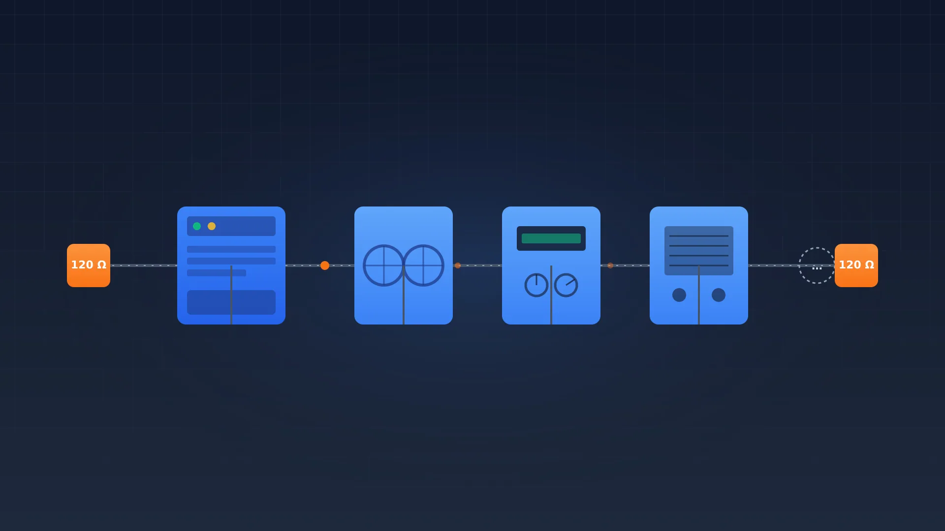
- All devices on one Modbus Extension share the same baud rate, stop bits, and parity, and the last device gets a 120 ohm termination resistor.
What is a Loxone Modbus integration?
A Loxone Modbus integration is the bridge between the Loxone Miniserver and industrial equipment that speaks Modbus, such as energy meters, heat pumps, and ventilation units. Loxone offers two routes for this, and you should not mix them up.
The first route is the Loxone Modbus Extension, a DIN-rail module that talks to the Miniserver over Loxone Link and has an RS485 terminal on the other side. The Extension is the Modbus RTU master and polls up to 32 devices on a single bus (source: Loxone KB, Modbus Extension). The second route is Modbus TCP: the Miniserver addresses an IP device directly as a network device, with no extra hardware, as long as both sit on the same LAN.
If you want to understand the protocol itself first, read Modbus RTU explained and Modbus TCP explained. For the wider picture of Modbus in a building, the building automation guide is ready.
Modbus Extension or Modbus TCP: which do you pick?
The choice between the Modbus Extension and Modbus TCP follows the device's physical layer, not taste. An RS485 energy meter can only go through the Extension, and an IP heat pump can only go through TCP.
| Feature | Modbus Extension (RTU) | Modbus TCP |
|---|---|---|
| Physical layer | RS485, twisted pair | Ethernet, LAN |
| Extra hardware | Modbus Extension required | none, direct on Miniserver |
| Max devices | 32 per Extension | limited by Miniserver load |
| Typical devices | energy meter, buffer sensor, ventilation | heat pump, inverter, IP meter |
| Wiring | terminate 120 ohm, max 1,200 m | regular network cabling |
Example: heat pump and energy meter in a home
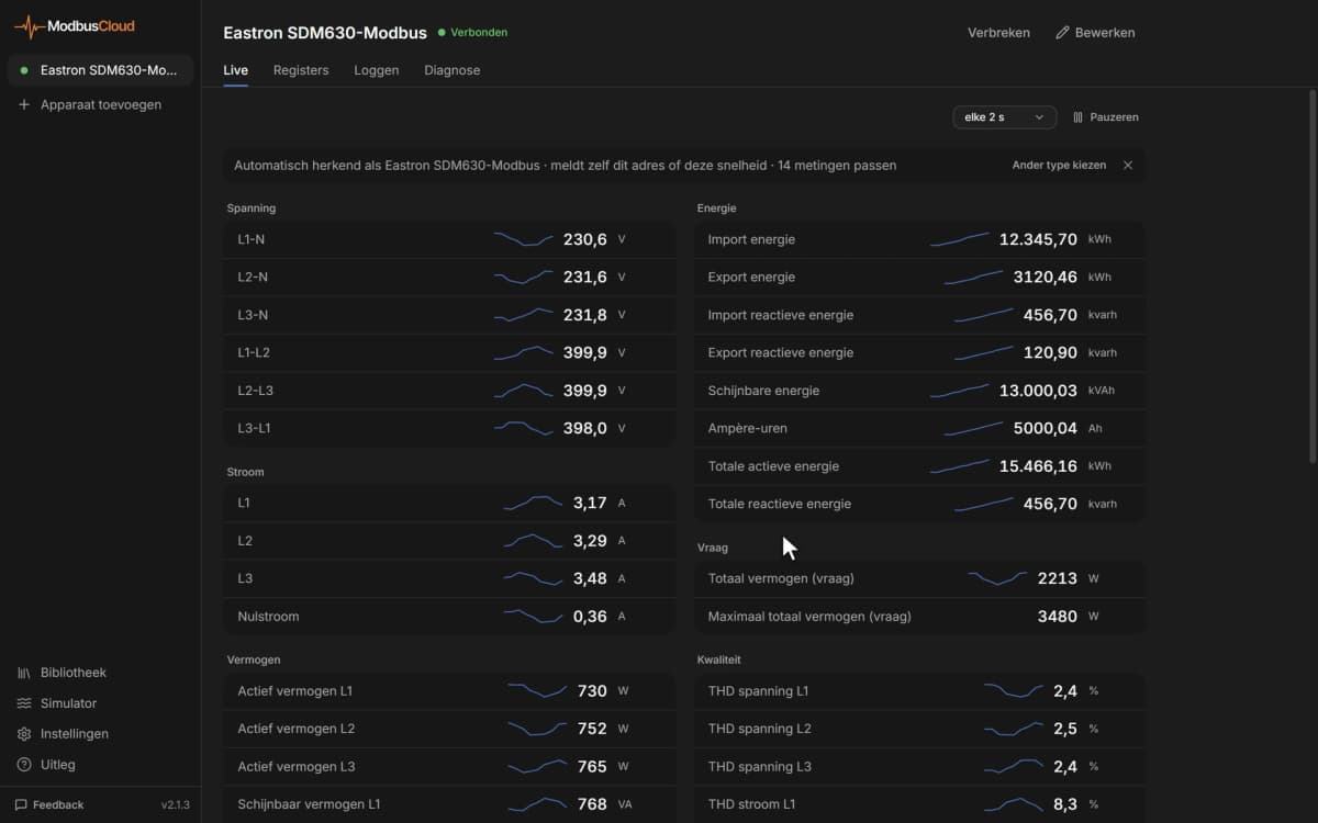
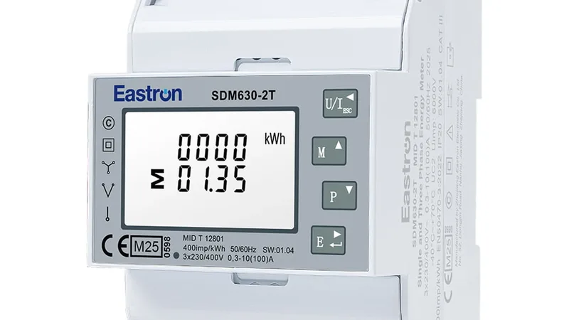
A Viessmann or Daikin heat pump with a Modbus TCP interface sits on the LAN and comes in as a network device. An Eastron SDM630 three-phase energy meter in the meter cabinet only speaks RS485 RTU and goes on the Modbus Extension. That way both paths run side by side in the same Loxone project. For a comparison of suitable meters, see the Modbus energy meter comparison.
Setting up the Modbus Extension on the RS485 bus
The Modbus Extension is an RS485 master, and RS485 sets hard requirements for wiring and termination. Skip them, and you get unreliable readings that only surface when the customer calls.
What you need
- A Loxone Miniserver with free Loxone Link capacity and a Modbus Extension.
- A twisted pair from a Cat 5, 6, or 7 cable for the RS485 bus (source: Loxone KB, Communication with Modbus). More on cable choice is in RS485 cable selection.
- A 120 ohm termination resistor for the last device on the bus.
- The register list of each device, from the manufacturer.
Step by step: adding the Extension
- 1
Mount the Modbus Extension on the DIN rail
Power the Extension with 9 to 28 V DC and connect it to the Miniserver over Loxone Link. The status LED flashes orange once the connection to the Miniserver is up.
- 2
Wire the RS485 bus
Land the twisted pair on the RS485 terminals and run the bus from device to device. Place a 120 ohm termination resistor on the last device. Keep the total length under 1,200 m.
- 3
Match baud rate, stop bits, and parity
All devices on the bus must share the same settings. The default baud rate is 19,200 with 1 stop bit. Set the device and Loxone Config to exactly the same values.
- 4
Give each device a unique address
Set a unique Modbus address on each device and enter that same address in Loxone Config. Two devices on the same address collide on the bus and give no reliable answer.
Configuring Modbus devices in Loxone Config
Configuring Modbus devices in Loxone Config means filling in the right fields per device, whether it is an RTU device on the Extension or a TCP device on the network. The approach is almost the same for both.
An RTU sensor under the Extension
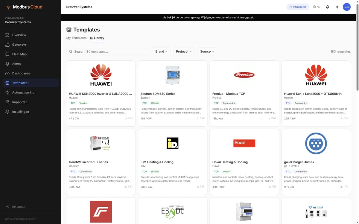
A Modbus sensor under the Extension is a read point that ties a register to a Loxone value. You add it under the Modbus Extension in the periphery tree, either manually or from a ready-made Template in the Loxone Library. Then you fill in four fields.
The information for the IO address, the command, and the data type is product specific and comes from the device manual. Since Loxone Config 14.4 you can lower the minimum polling cycle from 5 s to 1 s, and even to 0.1 s for up to two Modbus inputs per unit (source: Loxone Blog, Config 14.4).
A Modbus TCP device as a network device
A Modbus TCP device does not go on the Modbus Extension, but straight on the Miniserver as a network device. That is the route for IP heat pumps, inverters, and meters with Ethernet on board.
You add it under Network Periphery as a network device of type Modbus Server, give it an IP address and port (usually port 502), and define the same kind of sensors underneath as with RTU: IO address, command, data type, and polling cycle. The Loxone Library holds ready-made Modbus TCP Templates, among them Carlo Gavazzi EM24 and EM340 energy meters. For the approach per heat pump brand, the heat pump Modbus monitoring guide helps.
Troubleshooting common problems
Most Loxone Modbus problems sit in wiring, addresses, or data types, not in the Miniserver. The table covers the three you meet most often.
| Symptom | Probable cause | Fix |
|---|---|---|
| No value, sensor stays empty | Wrong baud rate or address | Set device and Config to the same baud rate and a unique address |
| Nonsense values, for example 6,553 instead of 21.5 | Wrong data type or scale factor | Choose the correct data type and apply the scale factor |
| Value drops out at times, timeouts | Bus too long or not terminated | Fit a 120 ohm termination resistor, lower the polling |
If you see similar integration questions with KNX, the KNX to Modbus gateway guide is a good companion.
Connecting Loxone Modbus to ModbusCloud
Loxone runs the local automation and visualisation in the building, but it is not a monitoring platform for a fleet across multiple sites. That is where ModbusCloud comes in. The division of labour is clear: Loxone runs the building, ModbusCloud watches the equipment remotely.
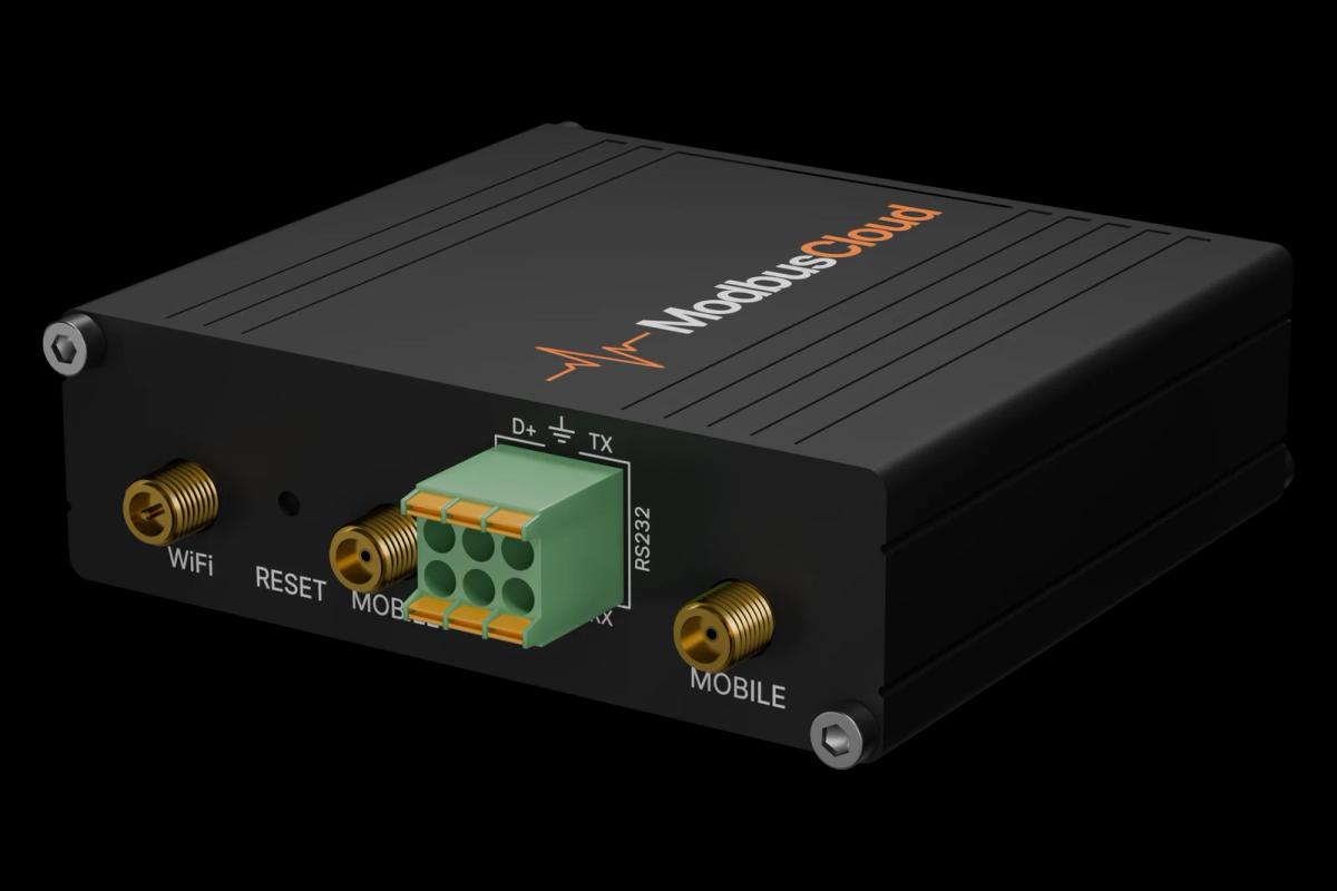
In practice, the ModbusCloud Gateway reads Modbus TCP devices in parallel with the Miniserver and sends the data encrypted to the ModbusCloud platform. On RTU there is exactly one master per RS485 bus, so the Gateway cannot read a bus the Modbus Extension already polls; connect those devices over Modbus TCP or put them on the Gateway's own RS485 line. That way you keep local control in Loxone and gain dashboards, alerts, and measurement history across multiple buildings on top. For a single home, the Home Assistant Modbus integration is an alternative, but for a service company watching dozens of installations the cloud layer is the difference between reactive and proactive maintenance.
Frequently asked questions
Does Loxone support Modbus TCP or only RTU?
Loxone supports both. The Modbus Extension does Modbus RTU over RS485, and the Miniserver addresses Modbus TCP devices directly as a network device on the LAN. For RTU you need the Extension, for TCP you do not.
How many Modbus devices can a Loxone Modbus Extension handle?
A single Modbus Extension supports up to 32 Modbus RTU devices on the RS485 bus. All devices must share the same baud rate, stop bits, and parity, and the last device gets a 120 ohm termination resistor.
What baud rate do you use for Loxone Modbus?
The default baud rate of the Modbus Extension is 19,200 with 1 stop bit. Set the device and Loxone Config to the same value. A lower baud rate is more stable on a long bus, a higher one gives faster readings.
Which four fields does a Modbus sensor have in Loxone Config?
Every Modbus sensor needs an IO address (the register), a type of command (the function code, usually FC03), a data type (16-bit, 32-bit, or float), and a polling cycle (the refresh interval). The manufacturer supplies the address and data type.
Can Loxone control a heat pump over Modbus?
Yes, provided the heat pump has a Modbus interface. An IP heat pump comes in as a Modbus TCP network device, an RS485 model on the Modbus Extension. With an actuator you write a setpoint through function code FC06 or FC16.
Do I still need a ModbusCloud Gateway next to Loxone?
Only if you want remote monitoring. Loxone solves local control. The ModbusCloud Gateway reads Modbus TCP devices in parallel with the Miniserver and sends the data encrypted to the cloud for dashboards, email or webhook alerts and 365 days of history. On RTU a bus has one master, so it cannot share the Extension's bus.