








All topics
On this page
The connections are on two sides of the gateway. The RS485 terminal and the antenna connectors are on one side. The power terminal and the network ports are on the other. The order in which you connect everything is described in Connect the gateway.
Connections
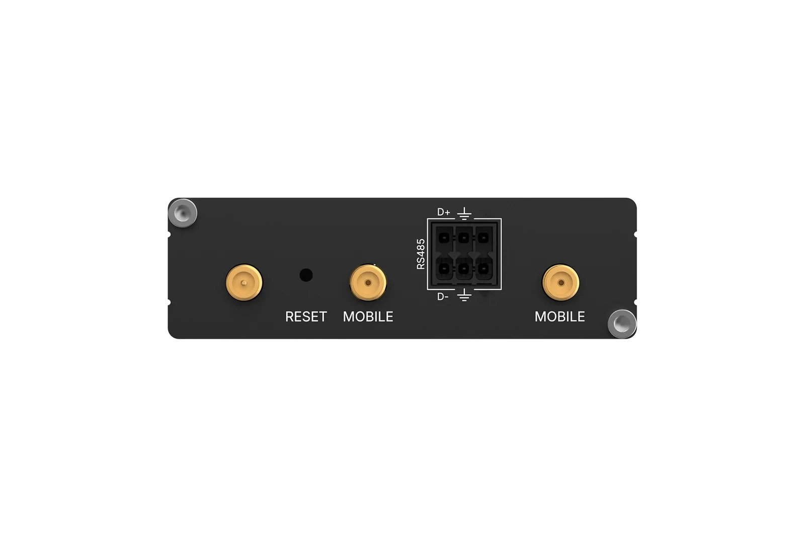
Side with the RS485 terminal and the antenna connectors
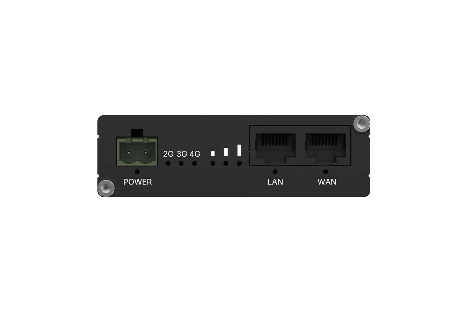
Side with the power terminal and the network ports
- RS485 terminal
- WAN port
- LAN port
- Antenna connector (MOBILE)
- Power terminal (POWER)
The table shows what each connection is for and how it is marked on the gateway.
| Connection | Marking | Use |
|---|---|---|
| RS485 terminal | RS485, D+, D- and the ground symbol | Modbus RTU devices on the RS485 bus |
| WAN port | WAN | Cable from the on-site network, for internet access and for Modbus TCP devices in that network |
| LAN port | LAN | A Modbus TCP device that you connect directly to the gateway. It gets no internet access through the gateway |
| Antenna connectors | MOBILE | 4G antenna, for the connection via the backup SIM |
| Power terminal, two-pole | POWER | Power supply for the gateway |
The gateway on the RS485 bus
The gateway is the Modbus RTU master on its own RS485 bus. A second master on the same bus does not work. If another system also needs to read the same Modbus devices directly, that only works with Modbus TCP devices in the on-site network.
The table shows what the gateway supports on the RS485 bus.
| Property | Value |
|---|---|
| Wiring | Half-duplex, with D+, D- and signal ground |
| Modbus devices per bus | Up to 32, the electrical limit of the bus |
| Slave address | 1-247, a separate address for each Modbus device |
| Baud rate | 1200, 2400, 4800, 9600, 19200, 38400, 57600 or 115200 |
| Parity | None (N), even (E) or odd (O) |
| Stop bits | 1 or 2 |
| Data bits | 7 or 8 |
| Default | 9600 baud, 8 data bits, no parity, 1 stop bit |
Baud rate, parity, stop bits and data bits apply to the whole bus. All Modbus devices on the bus therefore need the same settings. You set them for each gateway, as described in Gateway settings. How to wire and terminate the bus is described in Connect the RS485 bus.
Connection to the portal
The gateway sets up the connection to the portal itself, as an outbound connection from the site. It uses MQTT over TLS on port 8883 to a broker in Frankfurt. You do not need port forwarding or a fixed IP address. The traffic that the firewall must allow is listed in Network requirements for the gateway.
If the cable in the WAN port has internet access, the gateway sends its data over the cable. If there is no cable, or the cable has no internet access, the backup SIM takes over. ModbusCloud activates the SIM before shipping. How to connect the cable is described in Connect to the network via WAN and LAN.
Over the SIM, the gateway does not read values more often than the SIM interval, which is 300 seconds (5 minutes) by default. More about the SIM and the SIM interval is in 4G and the backup SIM.
Specifications
The table gives the technical data of the gateway, including certification and warranty.
| Property | Value |
|---|---|
| Power supply | 9-57 V DC, reverse polarity protected |
| Power consumption | Less than 2 W, at most 3.5 W |
| Ethernet | 2 ports, LAN and WAN, 10/100 Mbit/s |
| Mobile network | 4G LTE Cat 4 |
| Enclosure | Anodised aluminium, IP30 |
| Dimensions | 83 x 25 x 83 mm |
| Weight | 132 g |
| Operating temperature | -40 to 75 °C |
| Humidity | 10-90%, non-condensing |
| Mounting | On a 35 mm DIN rail, only with the DIN rail kit that you order separately |
| Certification | CE (RED), RoHS, WEEE |
| Warranty | 24 months from delivery, covering manufacturing and material defects |
How to mount the gateway and connect the power supply is described in Mount the gateway and connect the power supply. What the warranty does and does not cover is explained in Warranty and money-back guarantee.
Updated on 7 October 2026
Still stuck?
Email or call us. Include the serial number of the gateway, so we can take a look straight away.
Go to support