








All topics
On this page
Identifying, guessing and reading change nothing in the Modbus device. Diagnostics only sends read requests for these. Only writing changes something, and by default it asks for confirmation first.
What you need
- ModbusCloud Diagnostics on your computer, see Install ModbusCloud Diagnostics.
- A Modbus device that Diagnostics has found, see Connect and find a Modbus device with Diagnostics.
- For writing, the register map from the manual of the Modbus device.
Identify the device type
A device type is the register map of one model, which the portal calls a template. It records the name, address, data type, byte order, scale and unit of each register. Diagnostics knows 13 data types and four byte orders.
Identifying is a calculation on values that were read. Diagnostics reads the registers in which device types differ and checks which type fits what they contain, such as a mains voltage or a mains frequency. Over the network, Diagnostics also asks the Modbus device for its make and model, with function code 43 and the SunSpec marker. If the answer fits a type, that counts too. The library is stored on your computer, so identifying works without internet.
Identifying starts automatically as soon as Diagnostics has found the Modbus device. It stops when one type clearly wins or when there is nothing left to compare. At the latest, it stops after about 20 seconds on RS485 or 10 seconds over the network.
If one type wins, Diagnostics chooses it and opens the Live tab. Above the values you see the name of the type and why it fits. If the type is wrong, click Choose another type in that bar.
If Diagnostics is unsure, you choose yourself in the Add device window. The same cards appear on Live for a Modbus device without a device type.
Compare the candidates
Compare the values on each card with the display of the Modbus device. Each card shows Likely or Possible, with the reason after it.
Choose the type
Click Use on the type that is correct. The Modbus device opens on Live with the measured values of that type.
If the right type is not listed, you have four options.
- Search more thoroughly (takes up to a minute) reads for longer and also finds Modbus devices that answer slowly. The button appears if identifying stopped without a certain result.
- Choose a different device shows a search list with all device types. Search there by make or model.
- I have the manual adds the Modbus device and opens Read a manual, see Import the manual of an unknown Modbus device.
- Skip adds the Modbus device without a device type. Live tries again afterwards.
Sometimes the two registers of a 32-bit value are in the opposite order on a Modbus device than in the library. Diagnostics notices this while identifying. If it identifies the type with certainty, it saves a corrected copy as your own device type and Live shows the right values straight away.
Guess the registers
If no device type fits, Diagnostics guesses for each register which quantity it holds. You compare the guesses with the display and save them as your own device type.
The button for guessing appears on Live as long as the Modbus device has no device type and identifying found nothing, or only a type marked Possible. On the Registers tab, the same button is under Scan.
Open Live
Open the Live tab of the Modbus device.
Start guessing
Click Let the app guess what the registers mean. Diagnostics finds the registers, reads them a few times and assigns a quantity to each register, such as voltage, current or temperature.
Choose a kind
To steer the guesses, choose a kind under What kind of device is it?, such as Heat pump. Diagnostics guesses again with the registers it has already found.
Tick the correct values
For each value that matches the display, click the tick (Yes) next to Matches the display?.
Report a deviation
If a value does not match, click the cross (No).
Choose a correction
Under What does the display show?, choose the correction, such as ×10 or kW instead of W. If no option fits, click Fill in yourself.
Save the device type
Click Make this my own device type. Live reads these registers from now on.
The guesses appear under Likely, Possible and Not sure yet. If many registers show 0, put the Modbus device to work, for example under load, and click Guess again. Diagnostics recognises a device type you save this way by itself next time.
View live values
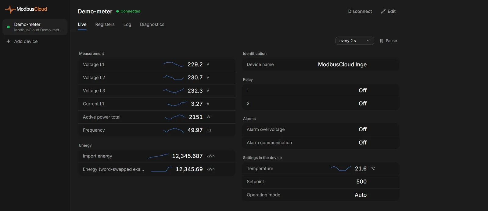
With a device type, the Live tab shows the measured values with name and unit, per group.
Choose the Modbus device
Click the Modbus device in the list on the left.
Open Live
Open the Live tab. The values refresh automatically.
Choose the interval
At the top right, choose how often Diagnostics refreshes, from every 500 ms to every 30 s.
Freeze the values
If you want to freeze the values, click Pause. Resume continues refreshing.
By default, Live refreshes every 2 seconds. You change that default in Settings under Default live interval. If reading a register fails for a moment, the last good value stays on screen in grey. If the Modbus device stops answering altogether, find the cause with Find faults with the Diagnostics tab and the console.
You record values over a longer period with Log and export with Diagnostics.
Read single registers
On the Registers tab you read any address, also without a device type. This is how you check an address from the manual.
Open Registers
Open the Registers tab.
Choose the register type
In Register type, choose Holding, Input, Coils or Discrete inputs. These are function codes 03, 04, 01 and 02.
Enter the start address
In Start address, enter the address as the manual writes it, for example
0,40001or0x0000. For a classic address such as40001, Diagnostics shows below the field which protocol address it reads.Enter the count
In Count, enter how many registers you read, up to 125 at a time. For Coils and Discrete inputs this can be up to 2000.
Read the registers
Click Read. The table shows the value of each address.
If you want to see which values change, click Repeat. Diagnostics then reads again every second.
Turn on Technical details for the hex value of each register. For registers without a name, the columns Int16, Float32 and Int32 then appear as well. Float32 and Int32 read the register together with the next one, in the most likely byte order. A star marks a plausible Float32 value.
With Technical details on, an arrow (Show all byte orders) appears at the end of a row. It shows the register and the next one as Float32, Int32 and UInt32 in all four byte orders, ABCD, CDAB, BADC and DCBA. The portal uses the same four byte orders and the protocol address, which counts from 0. How to enter them there is described in Enter a register address from the manual and Set the byte order and scale factor.
Write a value
Writing puts a new value in a register of the Modbus device, such as a setpoint or a setting. On Live you write to a register from the device type, on Registers to any address.
Choose the register
On Live, move the mouse over the value. For a writable register, a pencil (Write value) appears on the right.
Open the window
Click the pencil. The Write register window shows the current value.
Enter the value
In Value, enter the new value, in the unit that Live shows. Diagnostics converts the scale back itself.
Start writing
Click Write. Diagnostics shows the current and the new value side by side.
Confirm writing
Click Write again if the new value is correct. Diagnostics reports which value it wrote to which address.
On Registers, first choose Holding or Coils in Register type and click Write. In the window, you then enter Address, Data type and Value yourself. You set a coil to On (1) or Off (0).
Confirmation is on by default. If you turn off the Ask for confirmation before writing switch in Settings, Diagnostics writes at the first click on Write.
The table shows which function code Diagnostics uses for writing.
| What you write | Function code |
|---|---|
| One 16-bit register, such as uint16 or int16 | 06 |
| A value over several registers, such as float32 | 16 |
| One coil | 05 |
If the Modbus device rejects function code 06, open Technical details in the window. Select Write as a block (FC16) instead of a single register (FC06) there. For a coil, this option is called Write as a block (FC15) instead of a single coil (FC05). Under Technical details you also see the frame that goes over the wire.
Writing through the gateway is done in the portal, as described in Control registers from the portal.
Ask for make and model
Some Modbus devices report their make, model and firmware version on request. The Diagnostics tab asks for this in two ways, as part of the connection test.
The table shows which step uses which function code and what you get back.
| Step | Function code | Result |
|---|---|---|
| Ask for make and model | 43/14 | Vendor, Product and Revision |
| Ask for the device ID | 17 | A short identifier, as text or in hex |
Open Diagnostics
Open the Diagnostics tab. The test under Test connection starts automatically.
Read the result
Read the result next to Ask for make and model and Ask for the device ID. Vendor, product and revision appear below the test.
Repeat the test
If you want to ask again, click Test again.
If it says not supported (normal for many devices), the Modbus device does not answer that question. That is not a fault. What the other steps of the test say is described in Find faults with the Diagnostics tab and the console.
Updated on 7 October 2026
Still stuck?
Email or call us. Include the serial number of the gateway, so we can take a look straight away.
Go to support